Slin protocol – Baumer GXM7W User Manual
Page 5
Manual_RS485_SLIN_BIDE_EN.doc 5/7
Baumer IVO GmbH & Co. KG
04.05.11
Villingen-Schwenningen,
Germany
3. SLIN protocol
3.1. Technical
data
• bus interface according to RS485
• linear bus topology
• max. 8 bus users, selectable encoder address
• standard transmission rates: 9.6 kBaud, 19.2 kBaud and 115.2 kBaud
• bus access according to master / slave communication
• variable length of telegram
• data transmission asynchronous and half-duplex
• UART character format defined in line with IEC FT1.2 standard.
• data backup by parity and checksum
The physical bus is available to each user at a certain time only, since information might collide and become
illegible when being transmitted by several users at the same time. Consequently, the chronological order in
bus using time has to be regulated by bus access control. The SLIN protocol coordinates bus access
according to the master/slave principle. Every bus activity of passive users (encoders) is launched by master
(PLC, PC) using a control word.
3.2. Data
transmission
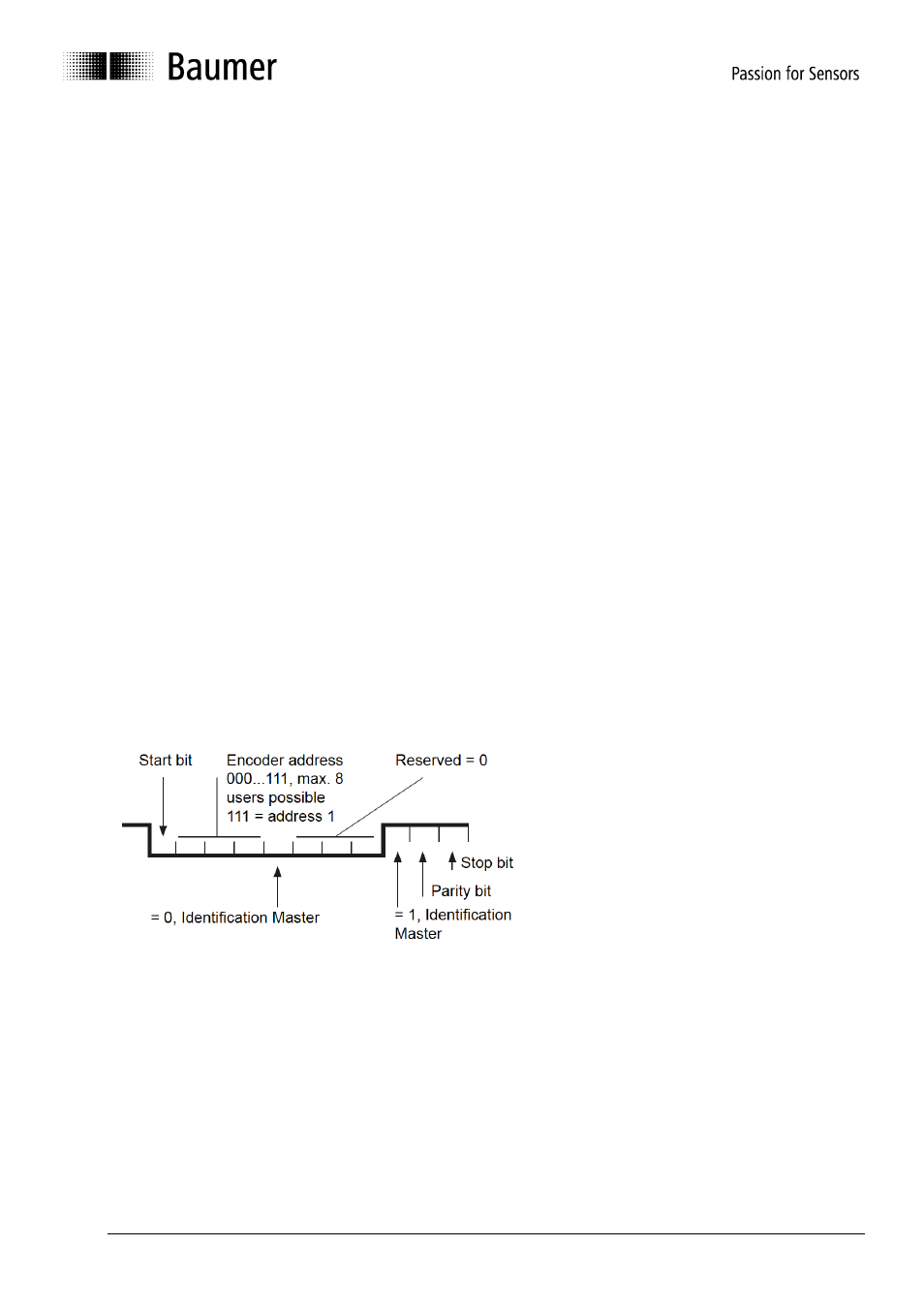
1. Master request
The control word comprises:
• 1 start bit
• 3 bits for the encoder address
• 1 control bit (low) master identifier
• 3 reserved bits (low)
• 1 control bit (high) control word identifier
• 1 parity bit, even parity
• 1 stop bit
The slave shall only transmit a response telegram when authorised by the above illustrated master request.
The encoder responds within 1 ms.
.