Installation instructions – EcoPure EP7140 User Manual
Page 10
10
COMPLETE INLET AND OUTLET PLUMBING
Measure, cut, and loosely assemble pipe and fittings
from the main water pipe to the inlet and outlet ports of
the water softener valve. Be sure to keep fittings fully
together, and pipes squared and straight.
Be sure hard water supply pipe goes to the water sof-
tener valve inlet side.
NOTE: Inlet and outlet are marked on the water sof-
tener valve. Trace the water flow direction to
be sure hard water is to inlet.
IMPORTANT: Be sure to fit, align and support all
plumbing to prevent putting stress on
the water softener valve inlet and outlet.
Stress from misaligned or unsupported
plumbing may cause damage to the
valve.
Complete the inlet and outlet plumbing for the type of
pipe you will be using.
COLD WATER PIPE GROUNDING
CAUTION: The house cold water pipe (metal only)
is often used as a ground for the house
electrical system, The 3-valve bypass
type of installation, shown in Figure 8,
will maintain ground continuity. If you
use a plastic bypass valve at the unit,
continuity is broken. To restore the
ground, do the following:
1. Install the included metal ground clamp across the
removed section of main water pipe, securely tight-
ening the hardware at the center (See Figure 13).
NOTE: Check local plumbing and electrical codes
for proper installation of the ground wire.
The installation must conform to them. In
Massachusetts, plumbing codes of
Massachusetts shall be conformed to.
Consult with your licensed plumber.
Installation Instructions
1. Measure, cut to needed length and connect the 3/8"
drain line (provided) to the salt storage tank over-
flow elbow and secure in place with a hose clamp.
2 Route the hose to the floor drain, or other suitable
drain point no higher than the drain fitting on the salt
storage tank (This is a gravity drain). If the tank
overfills with water, the excess water flows to the
drain point. Cut the drain line to the desired length
and route it neatly out of the way.
IMPORTANT: For proper operation of the water soften-
er, do not connect the water softener
valve drain tubing to the salt storage
tank overflow hose.
TEST FOR LEAKS
To prevent air pressure in the water softener and
plumbing system, complete the following steps in
order:
1. Fully open two or more softened cold water faucets
close to the water softener, located downstream
from the water softener.
2. Place the bypass valve (single or 3 valve) into the
"bypass" position. See Figures 7 & 8 on Page 7.
3. Slowly open the main water supply valve. Run
water until there is a steady flow from the opened
faucets, with no air bubbles.
4. Place bypass valve(s) in "service" or soft water posi-
tion as follows:
= Single bypass valve: Slowly move the valve stem
toward "service," pausing several times to allow
the water softener to fill with water.
= 3 valve bypass: Fully close the bypass valve and
open the outlet valve. Slowly open the inlet
valve, pausing several times to allow the water
softener to fill with water.
5. After about three minutes, open a hot water faucet
until there is a steady flow and there are no air bub-
bles, then close this faucet.
6. Close all cold water faucets and check for leaks at
the plumbing connections that you made.
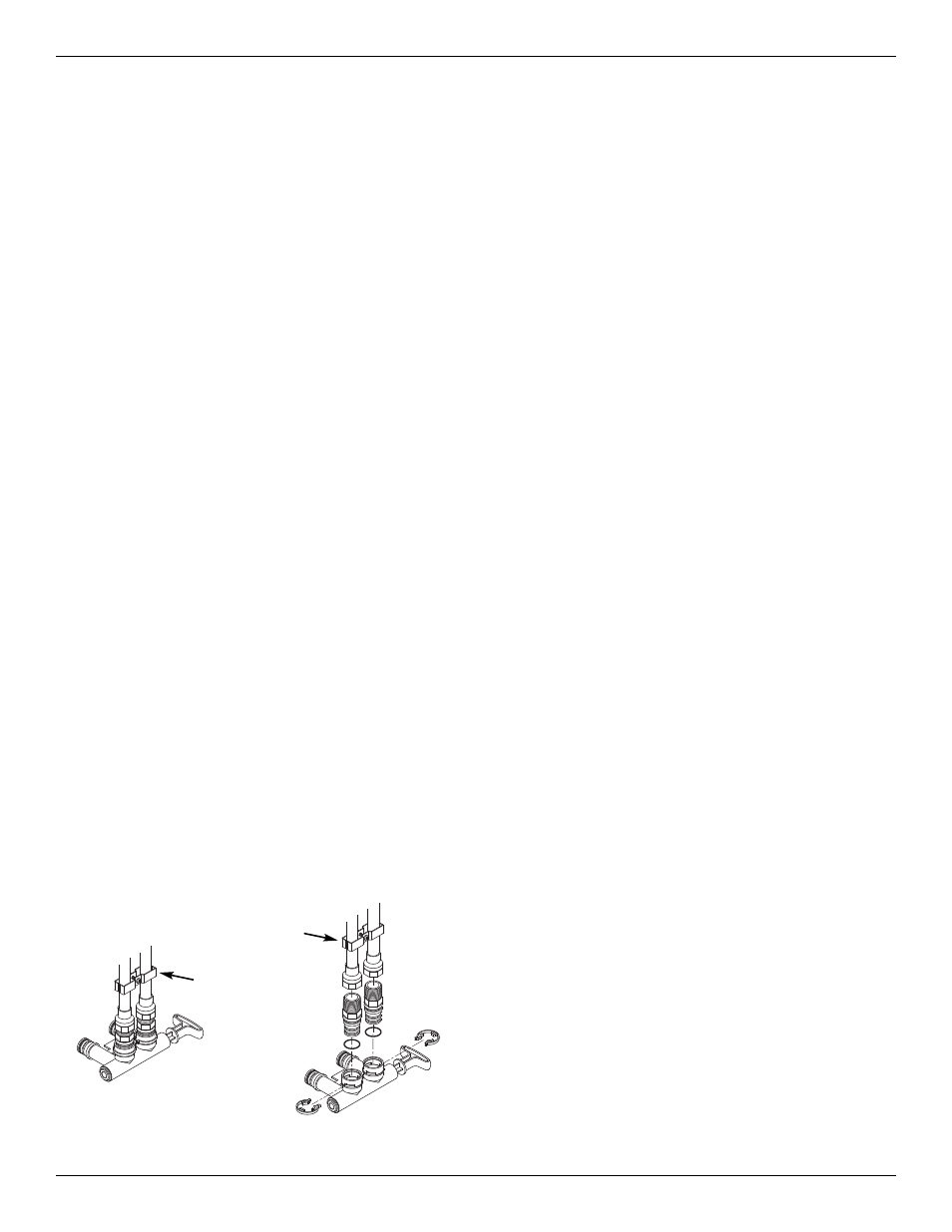
7. Check for leaks around clips at softener’s inlet and
outlet. If a leak occurs at a clip, depressurize the
plumbing (turn off the water supply and open
faucets) before removing clip. When removing clips
at the softener’s inlet or outlet, push the single
bypass valve body toward the softener (See Figure
14). Improper removal may damage clips. Do not
reinstall damaged clips.
INSTALL SALT STORAGE TANK OVERFLOW
HOSE
FIG. 13
Ground
Clamp
Ground
Clamp