Force chart, Model 755 relative centrifugal force chart – Drucker Diagnostics Model 755 Centrifuge User Manual
Page 14
14
Page 14
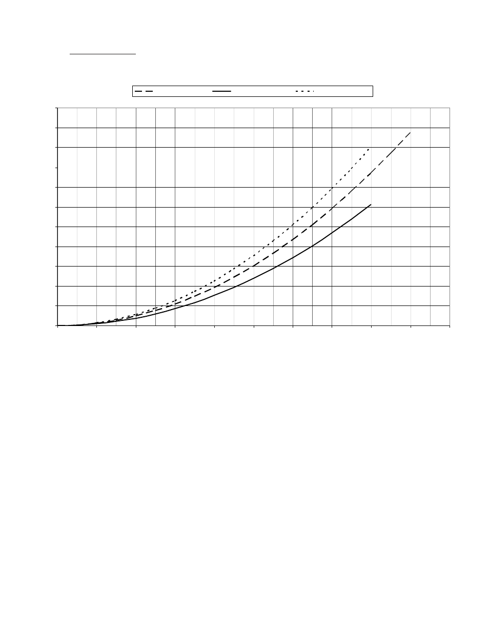
Force Chart:
This chart will allow you to set your Model 755 centrifuge to a desired g-force by
providing the appropriate speed for the rotor you are using.
Instructions for using this chart:
Find the desired force on the left-hand column and then follow across at that
level until you meet the line for the tube holder you use. Follow this intersection
point down to the bottom of the chart to reveal the speed required to produce
that force.
*
The graph shows the RCF, (relative centrifugal force), when using the 100mm red
tube holder. The use of different tube holders and / or cushions will alter the RCF.
Model 755 Relative Centrifugal Force Chart
0
200
400
600
800
1000
1200
1400
1600
1800
2000
2200
0
400
800
1200
1600
2000
2400
2800
3200
3600
4000
Spee d (RPM)
R
C
F
(x
g)
12 Place Horizontal
20 Place Fixed Angle
24 Place Horizontal
Force Chart:
Model 755 Relative Centrifugal Force Chart
This chart will allow you to set your Model 755 centrifuge to a desired g-force by
providing the appropriate speed for the rotor you are using.
Instructions for using this chart:
Find the desired force on the left-hand column and then follow across at that
level until you meet the line for the tube holder you use. Follow this intersection
point down to the bottom of the chart to reveal the speed required to produce
that force.
*
The graph shows the RCF, (relative centrifugal force), when using the 100mm red
tube holder. The use of different tube holders and / or cushions will alter the RCF.