CTEK Automation Control Application APN007 User Manual
Page 20
Application Note – Automation Control Application
APN007 25 July, 2014
15
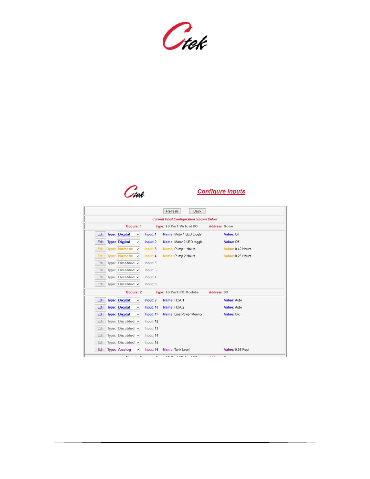
Configure Inputs
This is a selection screen. Use the Type pull-down and Edit button to select a specific Input for
edit. To completely disable an Input select Disabled in the pull-down and then press the
associated edit button.
The default display shows the current status of Inputs across all modules. Input pins are assigned
numbers and displayed sequentially starting with the first module installed
Note that the active individual inputs are color coded"
Purple
= Analog Input
Green
= Pulse Input
Blue
= Digital Input
Figure 16 - Input Configuration Screen
Input Configuration Screens
Figures 8 – 11 below show the configuration screens for the supported Input types,
physical/digital, physical/analog, physical/pulse, virtual/digital, and virtual/numeric. Following the
screen images is a complete list of attributes found on these screens and a description of their
application on a specific type of pin.