Typical sensor output, 7 commissioning, 8 service and maintenance – Cooper Instruments & Systems LXT 971 Rotating Torque Load Cell User Manual
Page 5: 9 handling and transportation, 10 precautions
CF 59
5
Rev. I September 2013
the maximum rotational speed. By compliance with the specification the sensor works generally trouble-free and
maintenance-free.
7.6 Irregular Operation, Measures against Disturbance
The presence of external
electromagnetic or magnetic fields can lead to irregular measurement results. The mechanical overload on the
sensor (e.g. exceeding of maximum allowed torque or severe vibrations) may cause damage to the sensor and
in consequence the incorrect signal output. In such cases please do not open the sensor. Contact Cooper
Instruments directly for assistance.
7.7 Commissioning
After sensor installation pay attention to the following:
• Switch on the power supply unit and check the supply voltage. Peak voltage must be avoided! Be sure
to verify the power supply voltage before connecting the sensor!
• Connect the sensor to the power supply unit by using the delivered cable.
• Connect the sensor output to a high-resistance device such as an A/D converter, oscilloscope, PC
measurement board. The sensor should be in mechanical unloaded state while connecting it.
7.8 Service and Maintenance
Contact Cooper Instruments at 800-344-3921
7.9 Handling and Transportation
In handling, storage and transportation, keep the sensor away
from magnetic or electromagnetic fields which may exceed the maximal intensity defined from EMC (see
Chapter 3. Technical Characteristics of the Sensor).
7.10 Precautions
• Do not open the sensor housing under any circumstances.
• Do not remove or loosen the locking rings on the shaft ends.
• Do not loosen or tighten the flange-mounting nut of the socket-connector and the fixing screws (1) (see
Chapter 5. Dimensions).
• Use only a separate power supply for the sensor.
• Use the sensor only according to the specification (Chapter 3. Technical Characteristics of the Sensor)
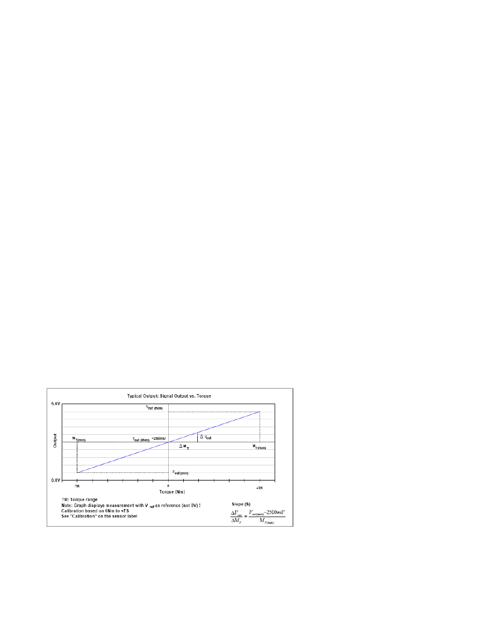
8. Typical Sensor Output
V
out(max)
and V
out(min)
are defined with the slope of the sensor. i.e. the output voltage could be between 0.5 V and 4.5 V.
The actual signal output range depends however on the calibration value.