Cooper Instruments & Systems DFI 7000 Digital Force Indicator User Manual
Page 8
CF11
8
V-May 2003-008-0186-00
7.1.1 Setting The Limits Adjustments
Proceed to adjust as follows:
1. Unplug the AC power and remove the bezel and front panel with a small screwdriver.
2. Depress the desired LIMITS pushbutton (L1 or L2) to display the current setting of the limit detector.
3. Adjust the proper (L1 or L2) limits potentiometer to give the desired limits value on the display.
4. Reinstall the front panel and bezel.
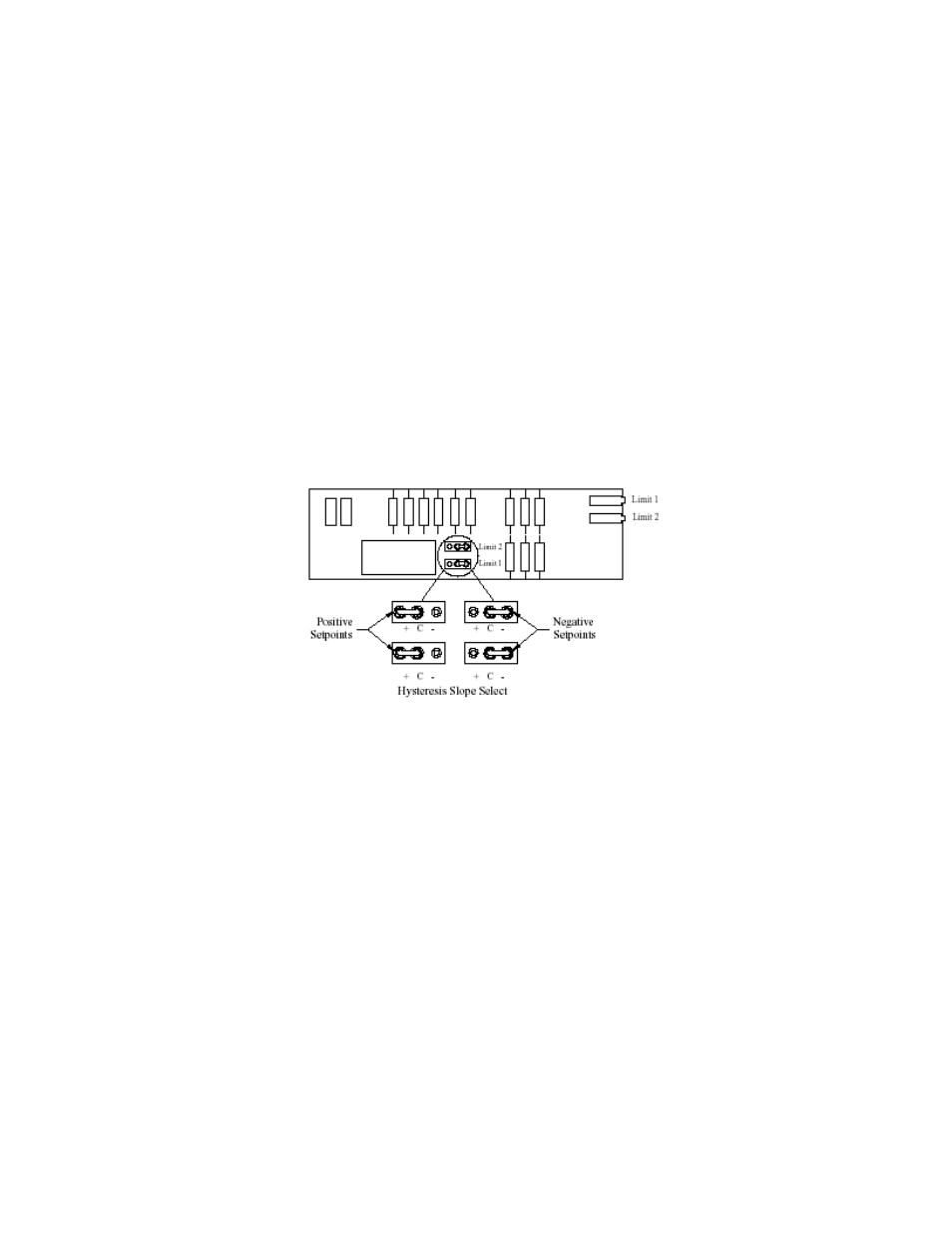
7.1.2 Limit Polarity And Hysteresis
If a limit de-energizes at the same level at which it is energized, a noisy input signal will cause the limit to oscillate,
eventually destroying the relays. For this reason, the DFI Limits Option contains “hysteresis,” a 1% difference
between the energizing point and the de-energizing point of the limit. This 1% difference should always be
between the limit point and zero. For a positively set limit, the signal would rise, activating the limit. When the
signal then drops, it must drop to 1% below the limit setting before the relay will de-energize. For negative
setpoints, where the setting of the limit is a negative value, it is necessary to reverse the hysteresis polarity. (See
figure 5.) At the factory, all limit hysteresis jumpers are set for a positive setpoint. If a negative setpoint is to be
used, proceed as follows:
1. Unplug the AC power and remove the bezel, front panel, and Main Board.
2. Remove the Limits Option Board.
3. Locate the hysteresis jumper for the particular limit (either high or low). Place the jumper in the correct location
to correspond to the limit setting for this limit.
4. Replace the Limits Option Board onto the Main Board.
5. Place the Main Board back into the case; reinstall the front panel and bezel.
Figure 5 – Hysteresis Jumpers On Limits Option Board
7.2 Peak Detector Option
The DFI 7000 Peak Detector Option detects the highest positive value that has been attained by the signal since
the peak detector was last reset. Reset may be accomplished by pressing the RST button on the front panel, or by
interconnecting the RESET and COMMON terminals momentarily on the rear connector. Further, the PEAK OUT
terminal will constantly monitor the peak detector output signal; the AMP OUT terminal and the display will monitor
the amplifier output normally, but will shift to monitor the output of the peak detector when one of two conditions
occurs:
1. The front panel PK button is pressed upward (momentary) or downward (locking).
2. The MODE SEL and COMMON terminals on the rear panel are interconnected.
7.3 Track-And-Hold Option
The DFI 7000 Track-and-Hold Option permits the DFI to stop tracking an input signal upon command. This
command can be issued by completing a contact closure remotely, or by front panel pushbutton.
When the Track-and-Hold feature is in the “hold” mode, the front panel HOLD light will be lighted. The HOLD
button on the front panel works alternately, so that one push will deactivate it. Potentiometers on Track-and-Hold
board permit small errors of zero and span to be turned out, so that true tracking results.
If it is desired that the “hold” feature be activated by rear panel means, connection of the HOLD terminal with the
COMMON terminal will cause the unit to go into HOLD mode. The OUTPUT signal terminals (rear connector) will