Cooper Instruments & Systems DFI 200 Hand Held Indicator User Manual
Page 5
CF 112
5
Version 3.1-0
scaling values may be entered for a single cell, allowing the same cell to display in different units e.g. Kilonewtons,
Kilograms and Tons. The user may select the load cell to be used via this
function or via the User
pushbutton if the pushbutton has been programmed for this purpose (see
function). To scale any of these
independent calibration memories you may use either the
and
methods or
the
method. Simply select the required cell number prior to scaling then scale using whichever
calibration method best suits the application.
The channel selected will always default to
(or
if external memory is used) at switch on. In addition
to independent calibration scalings for each channel selected each channel can be assigned different decimal point
(
), digital filter (
), mV/V input range (
) and sample rate (
) settings.
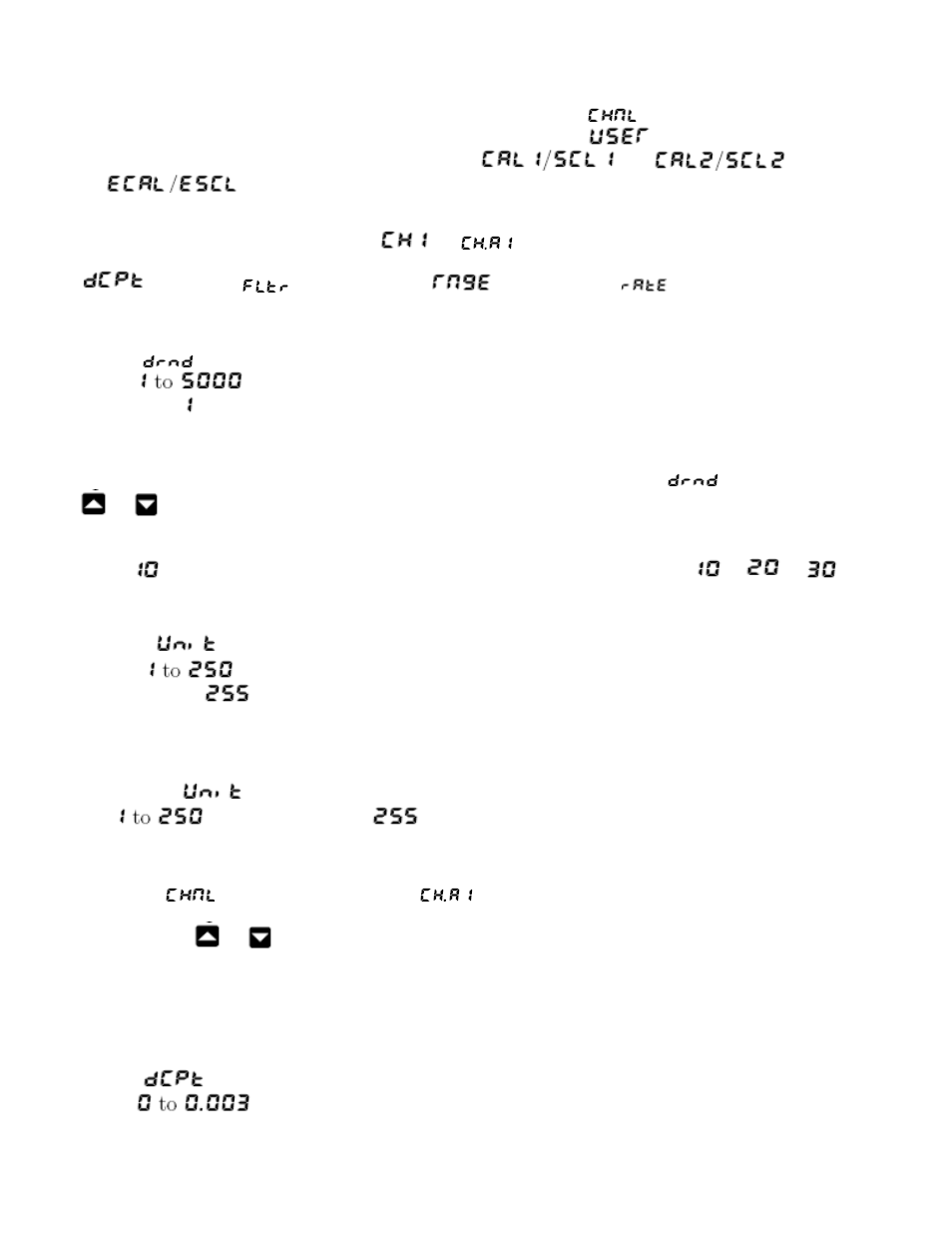
4.2 Display rounding
Display:
Range:
Default Value:
Displays and sets the display rounding value. This value may be set to 1 - 5000 displayed units.
Display rounding is useful for reducing the instrument resolution without loss of accuracy in applications where it is
undesirable to display to a fine tolerance. To set the display rounding value go to the
function and use the
or
push buttons to set the required value then press F to accept this selection.
Example:
If set to
the display values will change in multiples of 10 only i.e. display moves from
to
to
etc.
4.3 Memory chip address
Display:
Range:
Default Value:
This function is only seen when an external memory chip is connected. This function is used to display or set a unit
address to one or more optional external memory devices. For identification purposes each device should be
allocated a different address if more than one external memory is used. When a sensor with a memory chip is
plugged in the
function can be used to view the address of the memory device. The address can be set
from
. If the default address
is seen this indicates that the device has not had yet had an
address set. If a memory device has had an address set then the address can be viewed or altered at this function.
The procedure for setting or altering an address is as follows.
1. The
function must be set to either
i.e. a memory device must be connected.
2. With the external memory device connected enter function mode and step through to the Unit function.
3. Use
the
or
arrow to select the required address for that chip then press F to accept the change.
The address selected will now be stored in that memory device. The same address can be allocated to more than
one memory device and the address of a device can be changed at any time by following steps 1, 2 and 3 above.
4.4 Decimal point place
Display:
Range: