6 serial communications – Cooper Instruments & Systems DFI 200 Hand Held Indicator User Manual
Page 15
CF 112
15
Version 3.1-0
6 SERIAL
COMMUNICATIONS
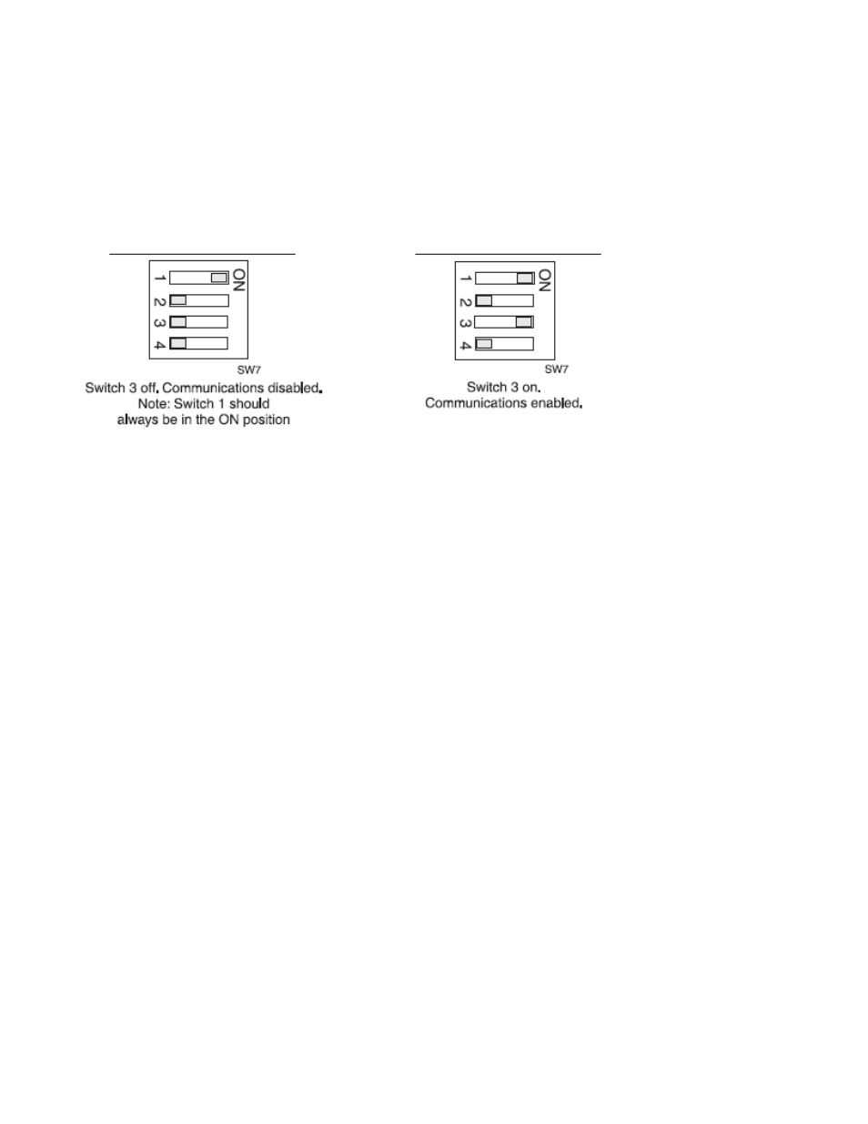
6.1 DIP switch settings
The RS232 communications can be enabled or disabled via a DIP switch SW7 located at the display end of the DFI
200 circuit board. Switch 3 of this DIP switch is used to switch the communications facility on or off as detailed
below. To gain access to the DIP switch remove the four screws at the rear of the DFI 200 case and remove the
back. The back is connected to the circuit board via a ribbon cable; there is no need to unplug this cable. Once the
back is removed SW7 should be visible at the top edge of the circuit board.
6.2 Electrical connections
The diagram below shows the electrical connections for a DFI 200 with both serial and load cell connectors. This
dual lead arrangement allows for a convenient connection to the load cell and RS232 serial port. Note: an adaptor
may be required to allow connection directly to a serial port.