Char-Broil 415.161209 User Manual
Page 18
18
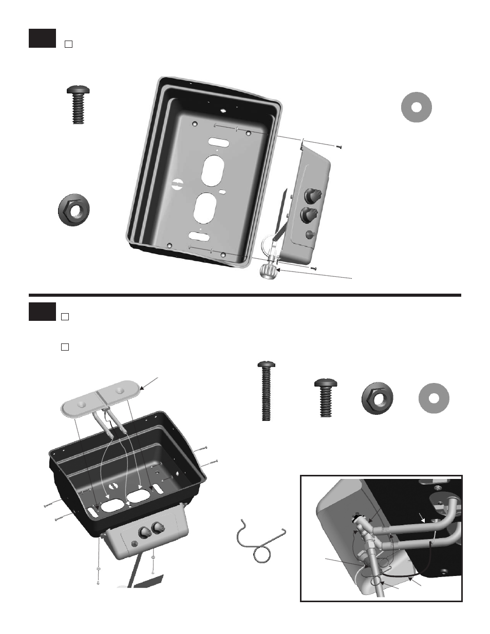
3
4
Control Panel
Attach control panel / HVR assembly to firebox with two #10-24x1/2’’ machine screws, 5x15 fiber washers and #10-24
flange nut.
Burner
Place burner assembly into firebox. Make sure burner tubes are correctly engaged with valves. Fasten the burner
assembly to the firebox using 5x15 fiber washers and #10-24x1/2’’ machine screws. Insert #10-24x1-1/4’’ machine
screws from outside the firebox, then fasten with #10-24 flange nuts and 5x15 fiber washers from the inside (A).
Insert one end of burner clip into hole in venturi tube and hook other end around valve manifold. Attach ignitor wire to
ignitor (B).
5x15
Fiber Washer
Qty.2
#10-24x1/2’’
Machine Screw
Qty.2
#10-24
Flange Nut
Qty.2
HVR Assembly
5x15
Fiber Washer
Qty.6
#10-24
Flange Nut
Qty.4
#10-24x1/2’’
Machine Screw
Qty.2
#10-24x1-1/4’’
Machine Screw
Qty.4
Venturi Clip
Qty.2
B
A
Burner assembly
Ignitor
Valve
Venturi
Tube
Venturi Clip
Ignitor Wire
- BIG EASY 4638213 (1 page)
- 463666512 (28 pages)
- INFRARED 8401504 (8 pages)
- 463741209 (32 pages)
- 463420509 (32 pages)
- Patio Caddie 06601295 (20 pages)
- 4984722 (1 page)
- 463257010 (32 pages)
- NATURAL GAS CONVERSION KIT 7116572 (24 pages)
- PATIO BISTRO 10601578-16 (8 pages)
- 4654870 (16 pages)
- 463232011 (32 pages)
- THE BIG EASY 4638263 (1 page)
- SILVER SMOKER 3201560 (16 pages)
- 463210510 (32 pages)
- RED 463250211 (28 pages)
- 463250511 (36 pages)
- AMERICAN GOURMET 10301580 (16 pages)
- 80015625 (28 pages)
- 466247310 (32 pages)
- 461111811 (12 pages)
- 463460708 (28 pages)
- PATIO BISTRO 11601579 (8 pages)
- 463230511 (32 pages)
- 4651330 (16 pages)
- 11301696 (20 pages)
- QUICKSET 463742704 (1 page)
- 463263111 (32 pages)
- COMMERICAL 463248708 (32 pages)
- BISTRO 10601578 (8 pages)
- 463272509 (28 pages)
- 463741008 (27 pages)
- 11601578 (8 pages)
- 463262911 (24 pages)
- GRILL2GO 11401587 (8 pages)
- 463247512 (28 pages)
- T-47D 463251012 (40 pages)
- 463270911 (28 pages)
- HEATWAVE 461262409 (28 pages)
- 463460711 (32 pages)
- 463621611 (28 pages)
- PATIO BISTRO 11601578 (8 pages)
- 463244012 (32 pages)
- 463222209 (36 pages)