Two-wire ready flow sensor installation – Baseline Systems BL-PFS200 Flow Sensor User Manual
Page 3
Installing the Sensor in the Pipe
The PVC flow sensor tee features socket ends intended for solvent welding into PVC piping systems. Use
best industry practices to ensure that the sensor is installed in the correct position with strong permanent
joints.
1-866-294-5847
Rev 03262013
www.baselinesystems.com
BL-PFS100, BL-PFS150, & BL-PFS200
Two-Wire Ready Flow Sensor Installation
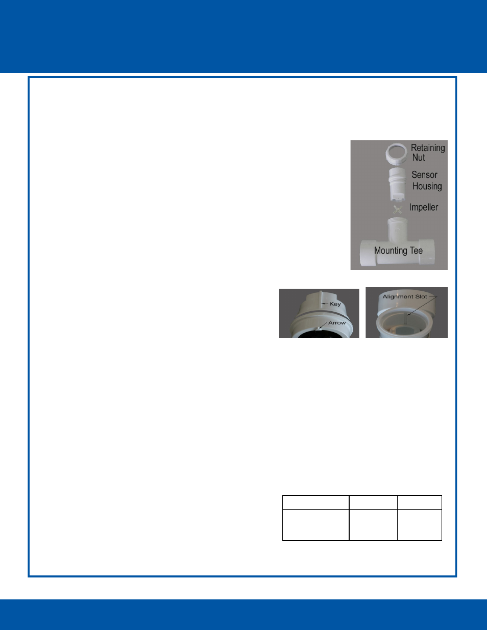
1. Disassemble the flow sensor before joining the tee to the piping system. To
remove the flow sensor housing from the tee turn the retaining nut counter
-clockwise to loosen it, and then pull the housing straight out of the tee.
Do not pull on the wire leads!
3. Use appropriate tools to cut the pipe. Remove all chips, filings, or cuttings
from the pipe.
4. Solvent weld the tee to the pipe using manufacturer’s recommendations.
5. After the joints have set, reattach the sensor housing to the tee. Make sure
the housing and tee are clean and free from dirt or debris. Position the
arrow on the top of the housing in the downstream direction. This aligns
the guide key on the housing with the slot inside the tee. Push straight in so
that the key enters the slot until the o-ring seals the opening.
6.
Slide the retaining nut over the wire leads and turn clockwise by hand to
tighten.
Making the Electrical Connections
1. Power off the two-wire when installing devices. Leave 24 to 36 inches of slack on the two-wire to allow
the PFS flow sensor housing to be removed from the tee and brought above grade for servicing.
2. Connect the red and black wire from the PFS flow sensor to the corresponding red and black wires on
the two-wire. It is critical that polarity is maintained. Do not connect flow sensor to power or valve
circuits!
3. Use wire nuts for your initial connections. After you verify communications between the BaseStation
and the PFS flow sensor, replace the wire nuts with DBR/Y or equivalent moisture-resistant connectors
for all two-wire path connections.
Do not use sealant or Teflon tape on the retaining nut
threads!
Programming the Controller
In the BaseStation 1000 User Manual, refer to Setting Up Flow
biCoders. If you want the PFS flow sensor to be associated
with a water source, refer to Assigning a Flow Sensor to a
Water Source.
In the BaseStation 3200 User Manual, refer to Searching for
and Assigning Flow Meters. If you want the PFS flow sensor to
be associated with a water source, refer to Assigning
Devices to Water Sources.
BL-PFS100, BL-PFS150 & BL-PFS200
Calibration Table
Model
K Value
Offset
PFS100
PFS150
PFS200
0.322
0.650
1.192
0.20
0.75
0.94