Ab c – B&G Zeus 12 User Manual
Page 22
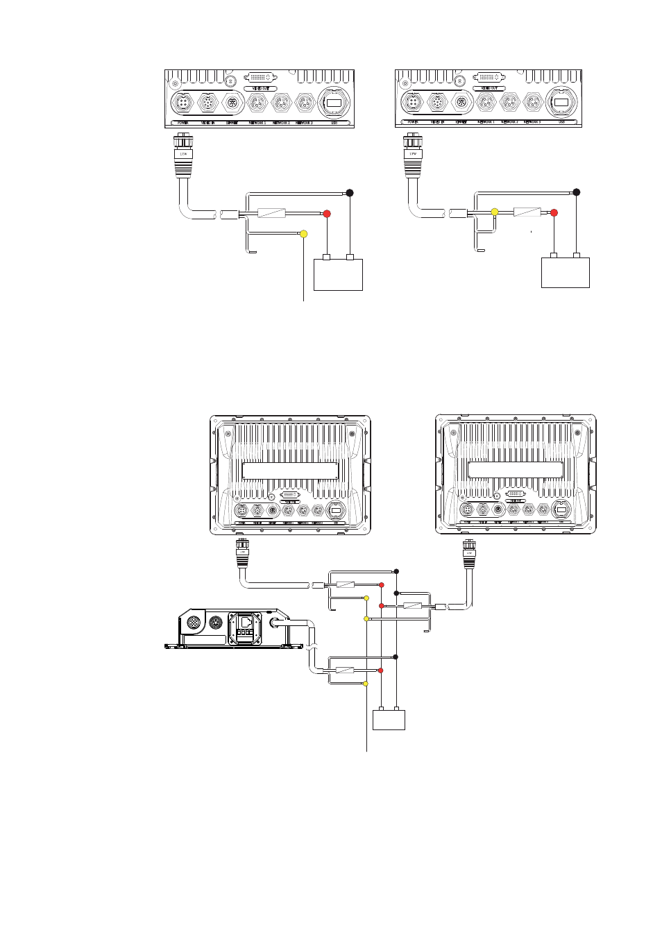
Wiring the Zeus Display
| 21
12 - 24 V DC
Red (FUSE)
Black
Yellow
No Connect
+ _
Blue
12 - 24 V DC
Red (FUSE)
Black
Yellow
Blue
+ _
No Power Control
Display will turn on and off when the
power button on the front of the unit
is pressed. Power Control wire is not
attached
Auto Power on
Display will turn on when power is applied
to the display. Common the yellow wire
with the red wire after the fuse.
Note: The unit can not be powered down
but can enter a standby mode.
12 - 24 V DC
Red
Black
Power Control Master
Power Control Slave
BR24 Radar
Yellow
Red
Black
Yellow
Red
Black
Power Control Bus
Yellow
+ _
A
B
C
Power Control Master
Display (A) turns on using the power button. It is set as the Power Control Master and
will output voltage on the Power Control bus to turn on display (B) and BroadBand™
Radar (C). Display (B) is set to Power Control Slave and if turned on by display (A)
cannot be powered down using its power button, but can be set to standby. If display
(A) is off, display (B) can be turned on using its power button, but won’t turn on any
other devices. Display (B) could, however also be set to Power Control Master.