Power – B&G Zeus 12 User Manual
Page 21
20 | Wiring the Zeus Display
Power
The Zeus displays can be powered by either 12 V or 24 V DC. Displays are protected
against reverse polarity, under voltage and over voltage.
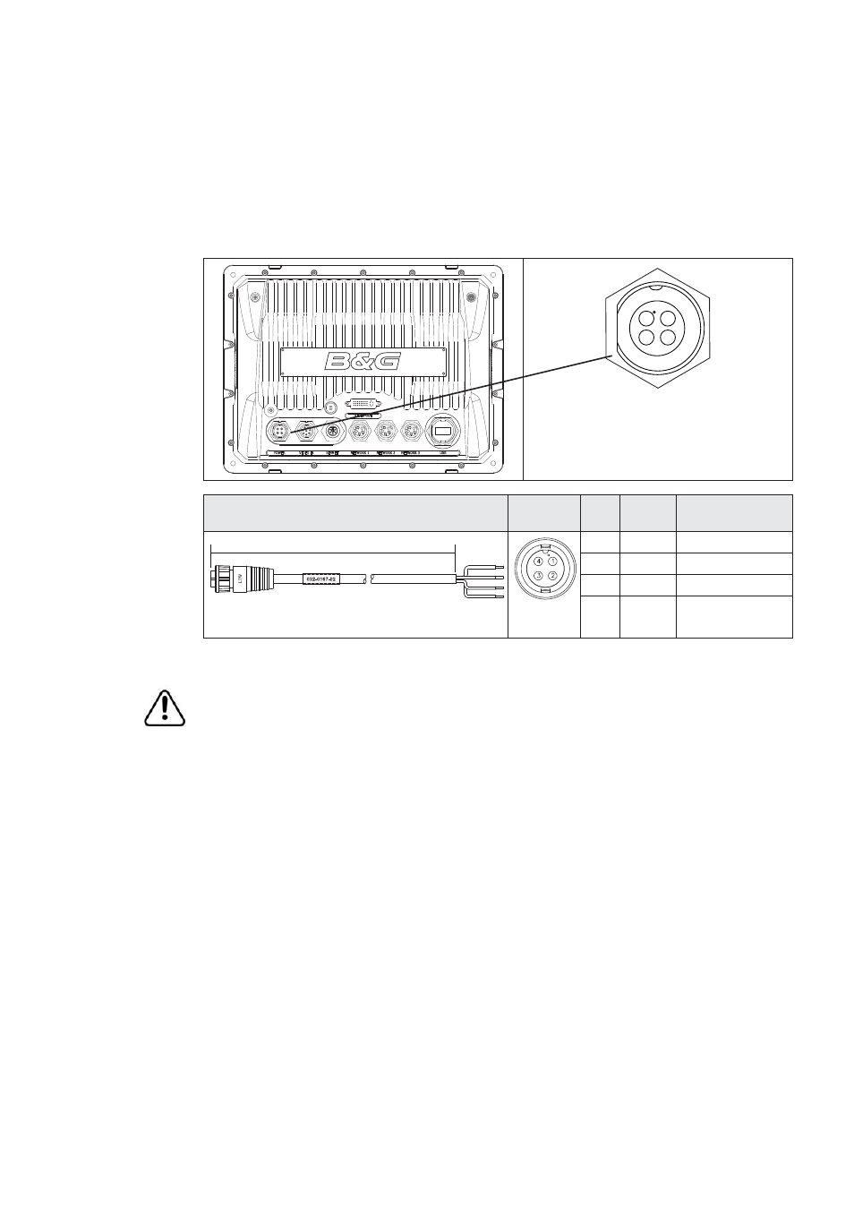
The supplied power cable has a four core cable used for:-
power into the system (Red and Black wires)
•
controling power state of the display or power state of other displays and devices
•
(Yellow wire)
connecting to an external alarm (Blue wire)
•
1 4
3
2
Power Cable (000-00129-001)
Con.
Pin
Wire
color
Function
2 m (6.5 ft)
1
Black
Battery (-)
2
Blue
External Alarm
3
Yellow
Power control
4
Red
Battery (+)
12 - 24 V DC
Connecting Power
The red wire should always be connected to (+) DC V using a fuse or thermal
breaker (10 Amp)
Power Control
The yellow (Power Control) wire can either be an input that will turn on the display when
power is applied, or an output that turns on other devices when the display is powered
on. It can be configured at the installation stage to control the power state of displays
and compatible devices. Planning is required how you want to be able to turn on and off
compatible devices. When commissioning the system, displays can be set to be a Power
Control Slave or Power Control Master.
Power Control configuration options are:-
Use the Power button to turn on the display only: Yellow wire not connected
•
Display to turn on when power is applied to the display: Common red and yellow wires
•
Use the Power button to turn on the display and other displays and or compatible
•
devices such as BroadBand™ Radar: Yellow wire connected to a Power Control Bus.
(Set one or more displays to be a Power Control Master)