Wiring the zeus display 8 – B&G Zeus 12 User Manual
Page 20
Wiring the Zeus Display
| 19
Wiring the Zeus Display
8.
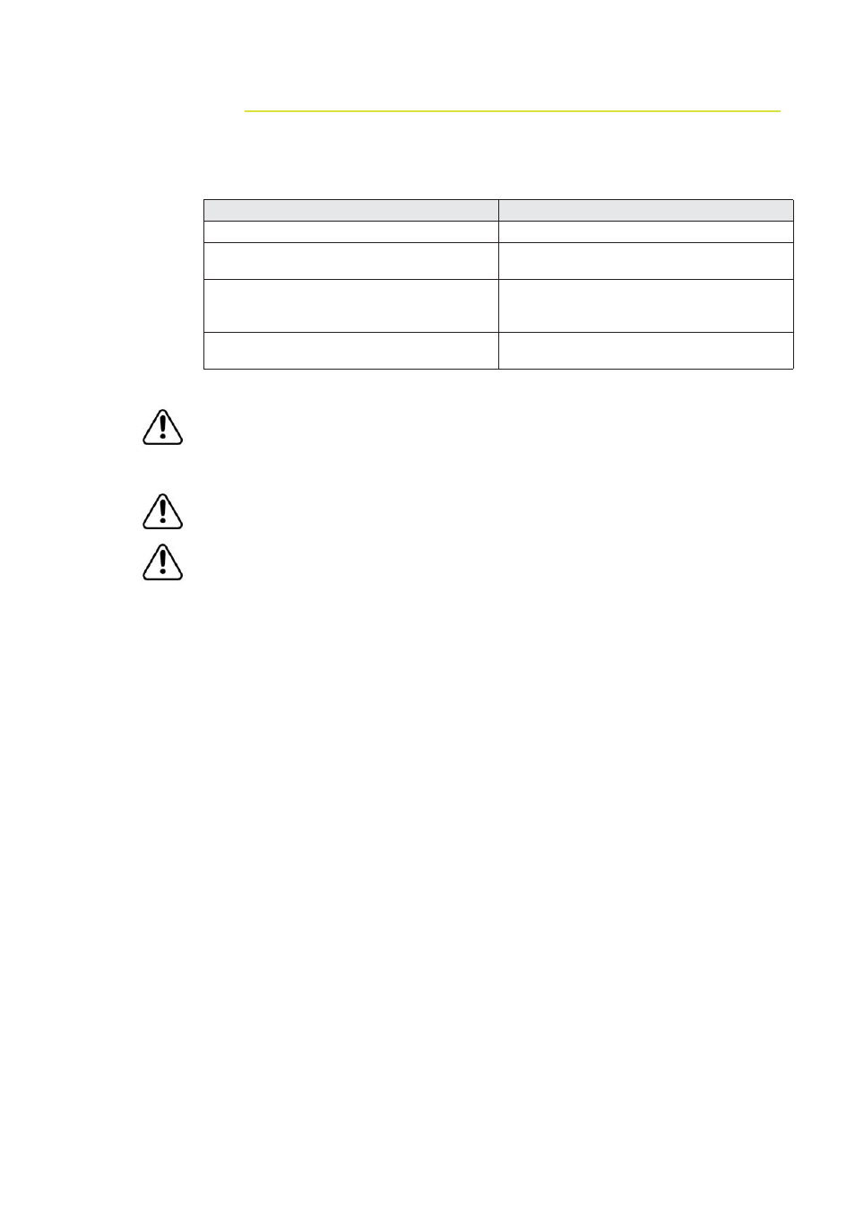
Wiring guidelines
Most installation problems are caused by shortcuts taken with system cables. When
wiring the Zeus, follow the guidelines below.
Don’t Do This
Do This
Don’t make sharp bends in the cables
Do make drip and service loops
Don’t run cables in a way that allows water
to fl ow down into the connectors
Do tie-wrap all cables to keep them secure
Don’t route the data cables in areas
adjacent to radar, transmitter or large
current carrying cables
If cables are shortened, lengthened, or
re-terminated, seal and protect all wiring
connections
Do leave room at the back to install and
remove cables
Before starting the installation, be sure to turn electrical power off. If power
is left on or turned on during the installation, fi re, electrical shock, or other
serious injury may occur. Be sure that the voltage of the power supply is
compatible with the Zeus display
The Zeus has a voltage rating of 12 V DC or 24 V DC. (9 V DC - 32 V DC max
range). NMEA2000 is 12 V DC only
The red wire should always be connected to (+) DC V using a fuse or thermal
breaker (10 Amp)