Ab c – B&G Zeus 12 User Manual
Page 14
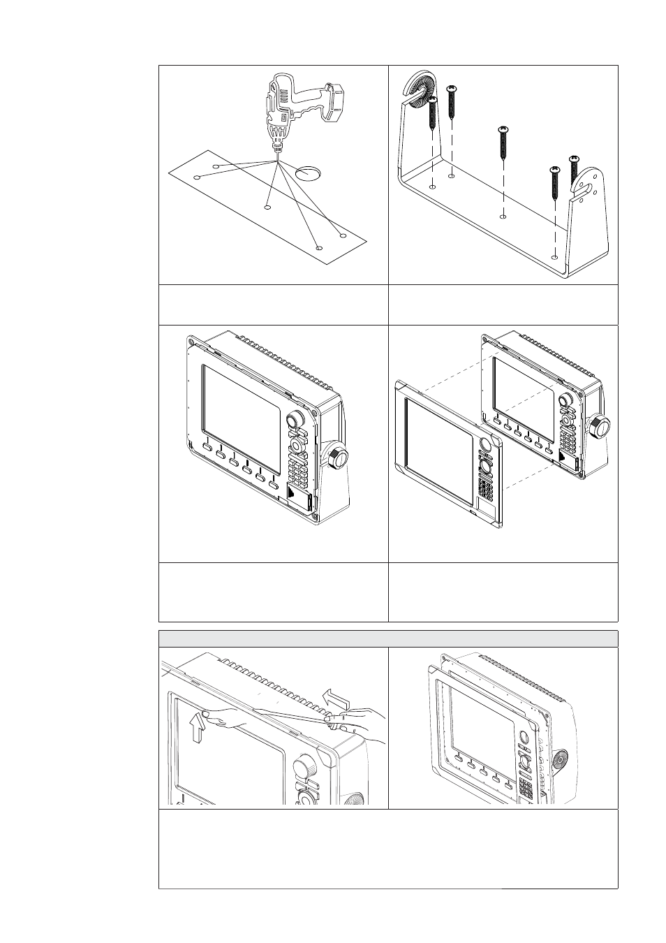
Installing the Display
| 13
Drill a pilot hole for the fi ve screws
5
and an optional hole large enough
for the cables to emerge from.
Secure 5 the bracket to the surface
6
Connect the cables.
7
Slide the display into the mounting
8
bracket and secure in place with the
bracket knobs.
Attach the bezel. Firmly clip the
9
front bezel in place.
Zeus Bezel Removal
A
B
C
Protect the dash area adjacent to the top edge (or bottom edge) of the display.
Apply upwards pressure on the bezel (A), this will create an opening between the
bezel and the case. Insert a medium size fl at blade screw driver into the gap (B) Slide
the screw driver along the gap to release the clips along the top. Continue down the
side until the bezel releases. The same routine can be applied to the bottom edge if
accessible.