Typical network example – B&G Triton Display User Manual
Page 14
12 |
Wiring |
IS40/Triton System Installation Manual
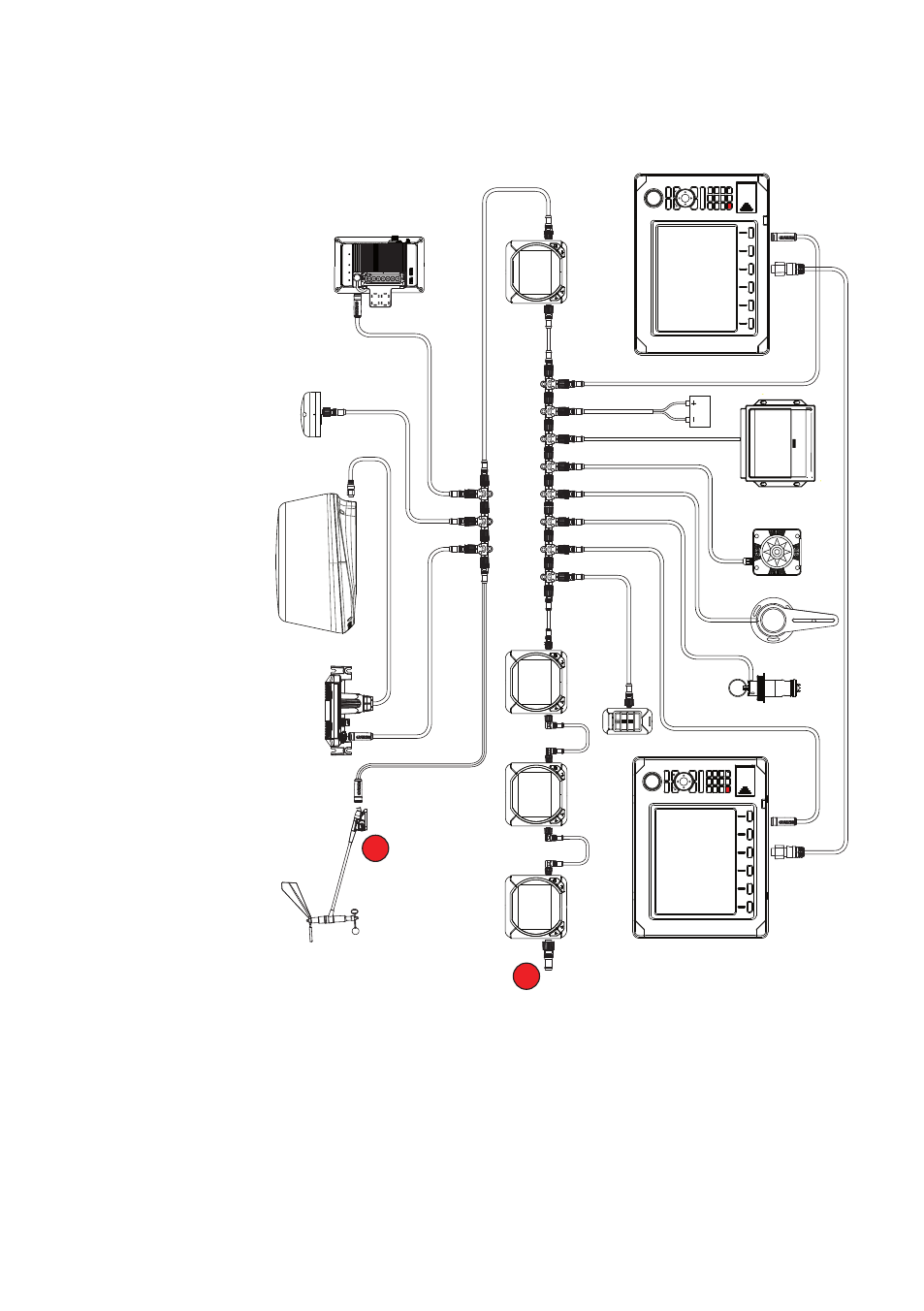
Typical network example
120
LTW
LTW
LTW
LTW
T
T
12V DC
¼
Notes:
•
The backbone must be terminated at both ends. The wind sensor
has a built-in terminator and can be used as one of the terminators
•
Daisy-chaining, as shown in this illustration, is recommended for
ease of installation. It will still be compatible with most NMEA 2000
devices but not fully comply with NMEA 2000 standard.