Description of modules: common to all alarms – Amico Valve Alarm Combo Unit User Manual
Page 8
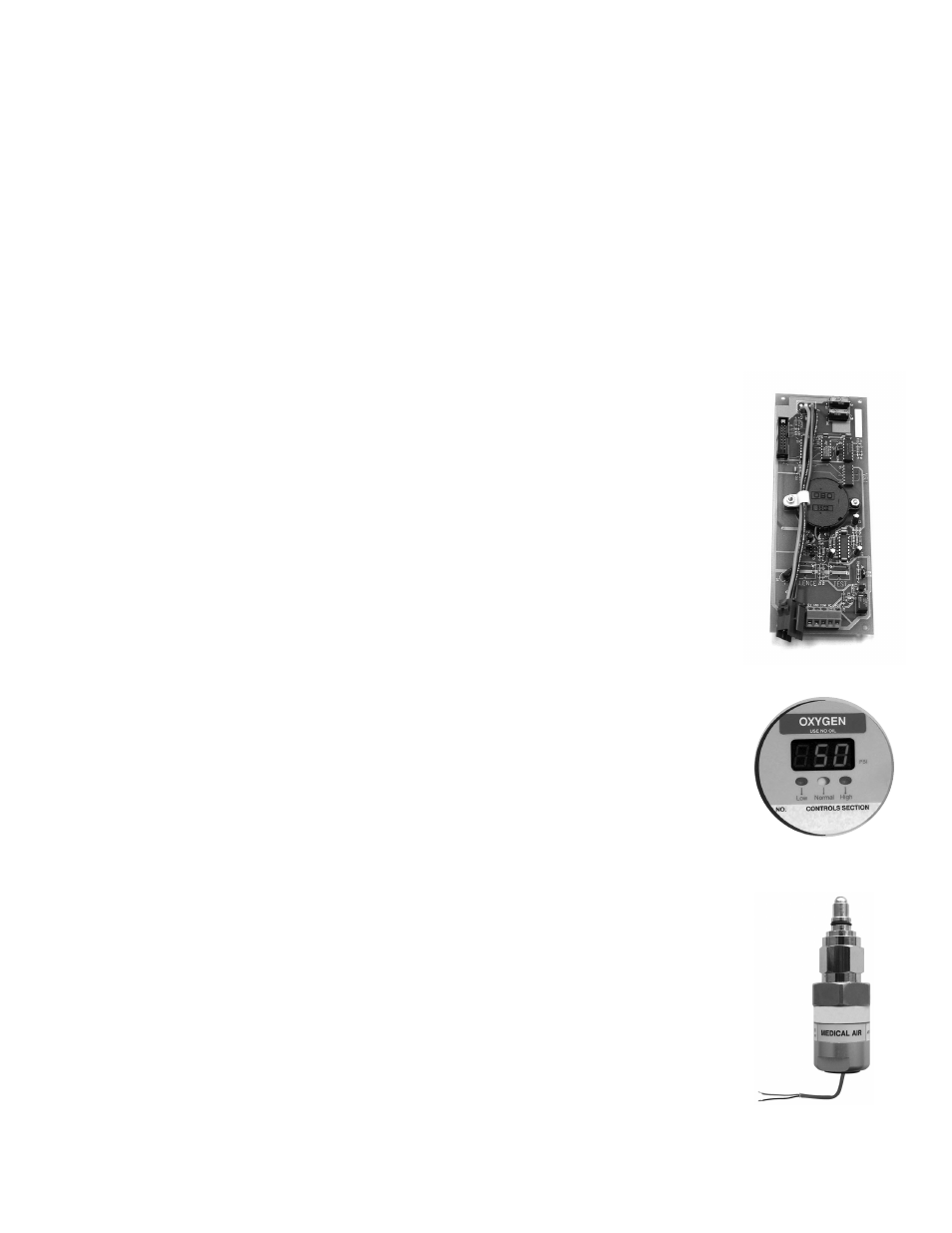
System Power Supply
The System Power Supply has been pre-installed into the back box assembly. The System Power Supply
converts the AC voltage supply to the alarm into two voltages: 5 VDC (regulated) required by the
microprocessor hardware and 15 VDC (unregulated) required by the buzzer and the LED’s. This unit also
contains the main ON/OFF power switch, the transformer, the heat sink, the main fuse and fuse cover, the
rectifying circuitry, the terminal blocks and the low voltage DC power cable for connecting this unit to the
annunciator module. The System Power Supply can be easily removed and reinstalled by unscrewing it from
the back box.
Annunciator Module
The Annunciator Module contains the buzzer, a “Power On” LED as well as the “TEST” and
“ALARM MUTE” buttons. The function of the “TEST” button is to verify that the buzzer and
all the LED’s are in working condition. An alarm will be heard when this button is pushed
and all the LED’s will light up. When the button is released, the alarm will silence. The
“ALARM MUTE” button is used to silence an alarm that has occurred. This module also
contains a fail-safe relay that de-energizes when the buzzer is activated. This relay can be
used with the Amico remote buzzer, for applications requiring a remote audible alarm
(see Appendix B), for connection to another Amico alarm or a building management
system.
Alarm Valve Display Module
The module provides a digital display of the actual pressure/vacuum of a gas being
monitored. In addition, a gas trend indicator bar with High and Low alarms are displayed.
The trend bar has two coloured LED’s: GREEN for Normal and RED for High and Low
conditions.
Each display module contains a gas specific, colour coded label (USA or ISO colours are
available). The Display Module is field adjustable for pressure/vacuum settings, repeat
alarm and unit of measure. Dry contacts for high and low alarms are available for remote
monitoring of each module.
Sensor Module
The Sensor Module contains the transducer which converts the gas/vacuum pressure
source into a digital signal that is displayed on the display module. The sensor module
shall be housed in an anodized aluminum and nickel-plated brass enclosure to act as an
interference barrier. It is also temperature compensated.
Each sensor is clearly labeled and colour coded for the gas or vacuum being monitored.
The sensor module contains a gas specific DISS fitting to ensure correct connection of
the proper sensor to the respective gas. Each sensor has been factory calibrated by a
computer for the specific gas shown on the sensor housing. If it is not connected to the
appropriate gas display module, an error message (EO2) will be displayed.
Description of Modules: Common to All Alarms
8
Amico Pipeline