Installation of alarm, Sensor, 250psi – Amico Valve Alarm Combo Unit User Manual
Page 10
CAUTION: The microprocessor circuitry on the alarm valve unit contains sophisticated integrated
semiconductors. If it becomes necessary to remove a module, PLEASE hold the boards by the edges.
DO NOT TOUCH any of the components on the board. Static discharge can cause the modules to
malfunction or become damaged.
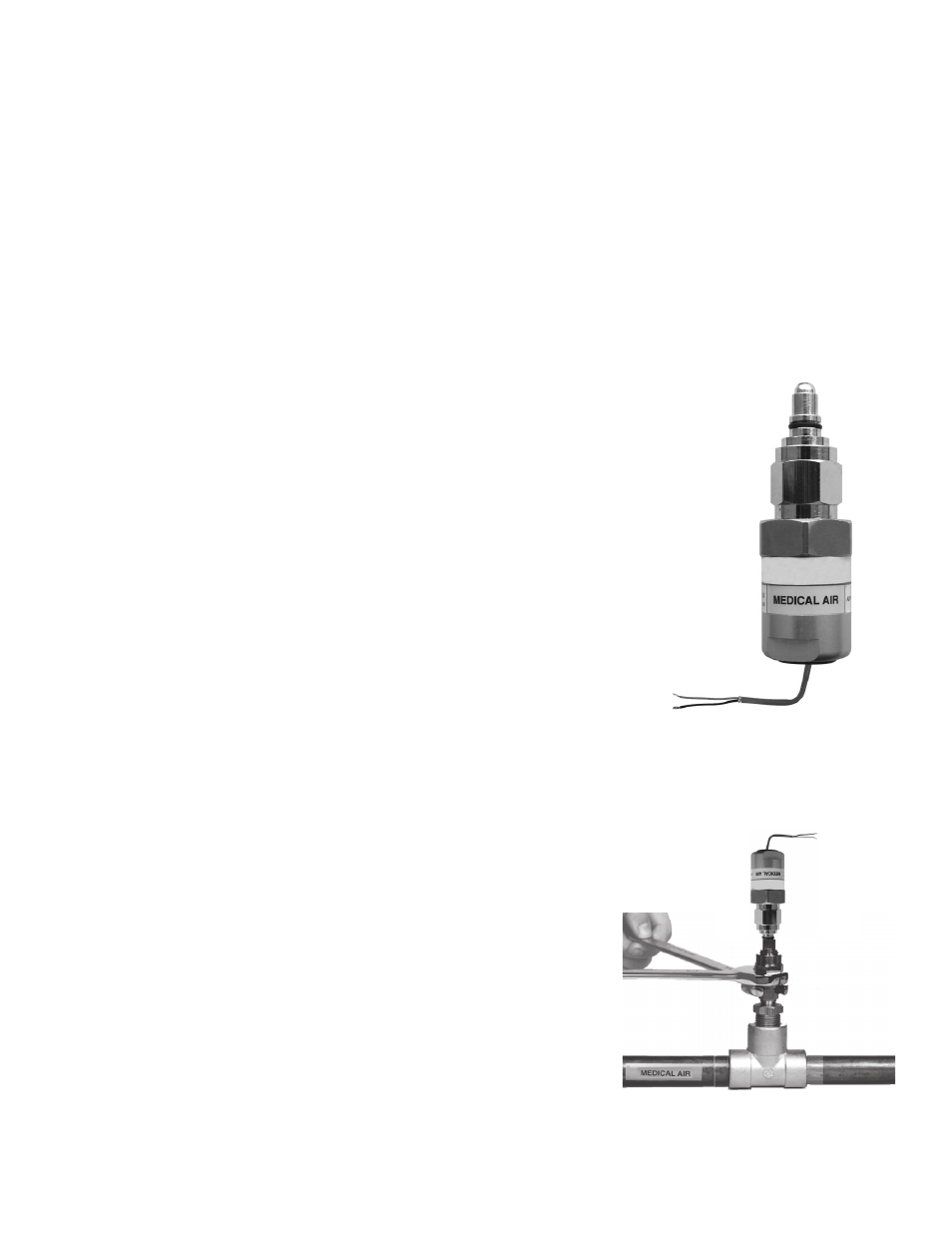
Sensor
LOCAL (Inside the Back Box)
1. Locate the gas specific sensor module to be installed.
2. In the back box, there are colour coded gas labels located under
the DISS Demand check valves. Each label identifies where each
sensor module is to be placed.
3. The sensor module contains a gas specific DISS fitting. Push the
sensor module hex-nut and nipple adapter up into the demand
check-valve. With a wrench, tighten the nut so that it makes a
good seal.
NOTE: Pressure on sensors is not to exceed 250 psi for pressure
sensors and 30" for vacuum sensors
The sensor can reach pressure up to:
Mid Pressure 0-99 Psi
Hi Pressure 0-249 Psi
Vacuum 0-30" Hg
REMOTE (Outside the Back Box)
1. Connect a Tee (supplied by others) to the pipeline with a 1/4" NPT
female connection that will accept the DISS Demand check-valve.
2. Locate the gas specific sensor module to be installed.
3. Thread the DISS Demand check-valve into the correct gas
pipeline.
4. The sensor module contains a gas specific DISS fitting. Push the
sensor module hex-nut and nipple adapter up into the demand
check-valve. With a wrench, tighten the nut so that it makes a
good seal.
A m i c o M i c r o p r o c e s s o r B a s e d A l a r m
P a g e : 1 2
CAUTION: The microprocessor circuitry on the ALERT-2 alarm con-
tains sophisticated integrated semiconductors. If it becomes necessary
to remove a module, PLEASE hold the boards by the edges.
DO NOT
TOUCH any of the components on the board. Static discharge can
cause the modules to malfunction, or become damaged.
SENSOR
LOCAL (In the Back Box)
1.
Locate the gas specific
sensor module to be in-
stalled.
2.
In the back box, there are
colour coded gas labels
located under the DISS
Demand check valves. Each
label identifies where each
sensor module is to be
placed.
3.
The sensor module contains
a gas specific DISS fitting.
Push the sensor module
hex-nut and nipple adapter
up into the demand check-
valve. With a wrench, tighten the nut so that it makes a good seal.
NOTE: Pressure on sensors are not to exceed
250psi
for Pressure sensors and
30”
for Vacuum sensors
REMOTE (Outside the Back Box)
1.
Connect a Tee (supplied
by others) to the pipeline
with a 1/4" NPT female
connection that will accept
the DISS Demand check-
valve.
2.
Locate the gas specific
sensor module to be
installed.
3.
Thread the DISS Demand
check-valve into the
correct gas pipe line.
4.
The sensor module contains a gas specific DISS fitting. Push the
sensor module hex-nut and nipple adapter up into the demand
check-valve. With a wrench, tighten the nut so that it makes a
good seal.
Installation of Alarm
10
Amico Pipeline