Heater specifications, Flue installation - standard flue kit – Cannon CANTFS-03-NG User Manual
Page 9
9
Gas type:
Natural or Propane gas, as indicated
on data label.
Gas consumption:
26 MJ/hr input.
Energy output:
21.45 MJ/hr (5.96 kW).
Energy star rating:
4 stars.
Heater type:
Approved to AS4553/AG 103.
Operating pressure:
Natural gas: 0.75 kPa.
(at the burner)
Propane gas: 2.65 kPa.
Gas regulator:
Integral part of controller.
Min. inlet pressure:
1.13 kPa (Nat Gas).
2.75 kPa (Propane).
Fan:
3 speed.
Controller:
Electronic direct spark.
Power requirement:
240 VAC 10 Amp.
Power consumption:
90 VA maximum.
Optional Accessories:
• Safety guard.
• Gold trim.
• Cathedral ceiling flue box (for standard flue
only).
Standard flue kit:
2 x 900mm lengths of 125mm ø painted
upper flue.
1 x 900mm length of 125mm ø plain flue.
1 x ceiling plate.
1 x 900mm painted bottom flue spigot length.
1 x 125mm ø flue cowl.
Alternative flue kit for
4 x 900mm lengths of 75mm ø inner
double skin flue:
galvanised flue.
1 x 850mm length of 170mm wide lower
outer flue cover.
2 x 850mm lengths of 170mm wide upper
flue cover.
1 x ceiling plate.
1 x 75mm ø flue cowl.
Heater specifications
8
Note:
The data label is
located on the rear
of the removable
pedestal front.
16
This heater is a flued appliance. It must be properly connected to a flue
system in accordance with the latest edition of the Gas Installation Code,
AS 5601/AG 601.
If elbows are required, we recommend 45° only and no more than two in
the total flue run, there should also be a minimum of 250mm straight flue
section in between bends..
If practical, locate the heater in a position to minimise the need for elbows.
There must be at least 1.8mm of vertical before any changes in direction of
the flue.
If placed against a combustible wall the 40mm rear spacers locate against
the wall.
1. Ensure clearances to combustible constructions have been observed.
For clearances refer page 10.
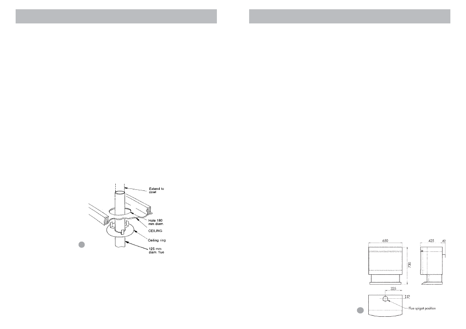
2. The centre line of the flue is 120mm to rear of appliance (including rear
spacers).
3. Carry out installation as per figure 25 (ceiling plate installation) and
figure 26 (flue installation).
Cut a hole 180mm ø in the ceiling in line with the flue position. Secure
ceiling plate against the ceiling by bending out the tabs above the
ceiling.
Note: If the ceiling has an incline, the ceiling box will need to be fitted.
The ceiling box is an accessory and can be ordered from the supplier.
Installation instructions are supplied with the ceiling box. Part no: BOXFB.
Flue kit
The flue kit contains:
2 x 900mm lengths of 125mm ø painted upper flue.
1 x 900mm painted bottom flue spigot.
1 x 900mm length of 125mm ø plain flue.
1 x ceiling plate.
1 x 125mm AGA approved gas cowl.
.0
Flue installation - Standard flue kit
25