Cannon CANTFS-03-NG User Manual
Page 13
12
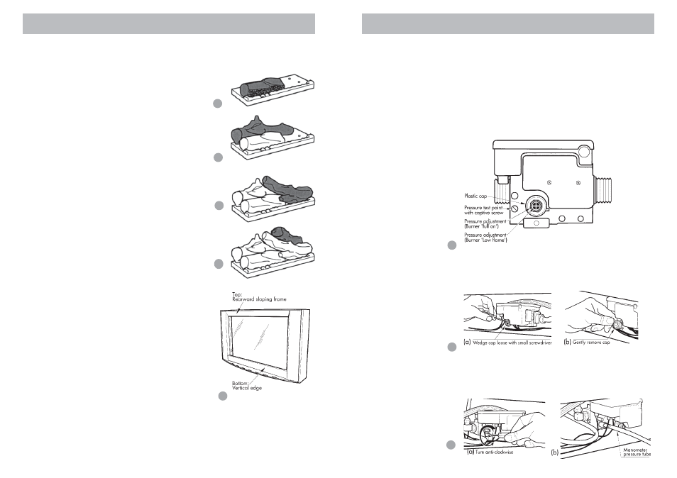
Position the four individually numbered logs in the following order on
the burner head as shown in figures 15 - 18. The male locating pins in
the burner head must engage with corresponding holes in the indi-
vidual logs.
a) Place log No.1 onto the 2 front left
pins on the burner head, ensuring that
the charring faces the front.
Refer figure 15.
b) Place log No.2 onto the 2 left
back pins. Refer figure 16.
c) Place log No.3 on single right
front pin, ensure fork locates over log
No. 2. Refer figure 17.
d) Place log No. 4 on single right
back pin, ensure left side of log rests
on depression in No. 3 log.
Refer figure 18.
13. Refit the inner glass, but do not
overtighten the screws.
14. Refit the front glass surround. En-
sure that the glass surround is re-
placed the correct side up. The
rearward sloping frame must be
at the top and the vertical edge
must be at the bottom. Refer figure
19.
Gas control
15. Gas control layout is as indicated in figure 20
Operate the heater on HIGH and LOW burner and all fan speeds.
The flame should be stable, no lifting from the burner, and the logs
should glow after approximately 15 minutes of operation on HIGH
burner.
15
18
19
17
16
Advise the user in the
operation of the heater.
13
If the flame is unstable:
❍ Check that the burner is located correctly.
❍ Check that the glass front is located correctly and is against the
sealing rope.
❍ Check that the gas pressure is correctly adjusted.
If the heater still does not operate to specification refer to the trouble-
shooting chart on pages 22 & 23, or contact Sampford IXL in your
state.
Pressures for ‘Burner full on’ and ‘Burner low flame’ are factory
set, however if pressures need to be checked or adjusted follow the
procedures described below and on the next two pages.
16. To check control outlet pressure at burner ‘Full on” and ‘Low Flame”
positions, remove the plastic cap from the regulator adjustment loca-
tion as indicated in figures 21 (a) & (b).
Gas pressure point
17. The pressure point is closed with a captive screw. Turn screw 6 revo-
lutions anticlockwise to open the pressure point as indicated on figure
22 (a) and place manometer tube over the test point as per figure 22
(b).
20
21
22