Section 1 preparation and setup, Prestart checklist, Hitching tractor to implement – Great Plains CP1000 Operator Manual User Manual
Page 12: Wiring drill
10
Section 1 Preparation and Setup
CP1000 Three-Meter Drill and Hitch 148-358M
7/5/2005
Great Plains Mfg., Inc.
End Piece
23252
Section 1
Preparation and Setup
This section will help you prepare your tractor and implement
for use.
Prestart Checklist
1.
Read and understand “Important Safety Information,”
page 1.
2.
Check that all working parts are moving freely, bolts are
tight, and cotter pins are spread.
3.
Check that all grease fittings are in place and lubricated.
Refer to Lubrication, “Maintenance and Lubrication,”
page 35.
4.
Check that all safety decals and reflectors are correctly lo-
cated and legible. Replace if damaged. See Safety De-
cals, “Important Safety Information,”
page 4.
5.
Inflate tires to pressure recommended and tighten wheel
bolts as specified. See “Appendix,” page 42.
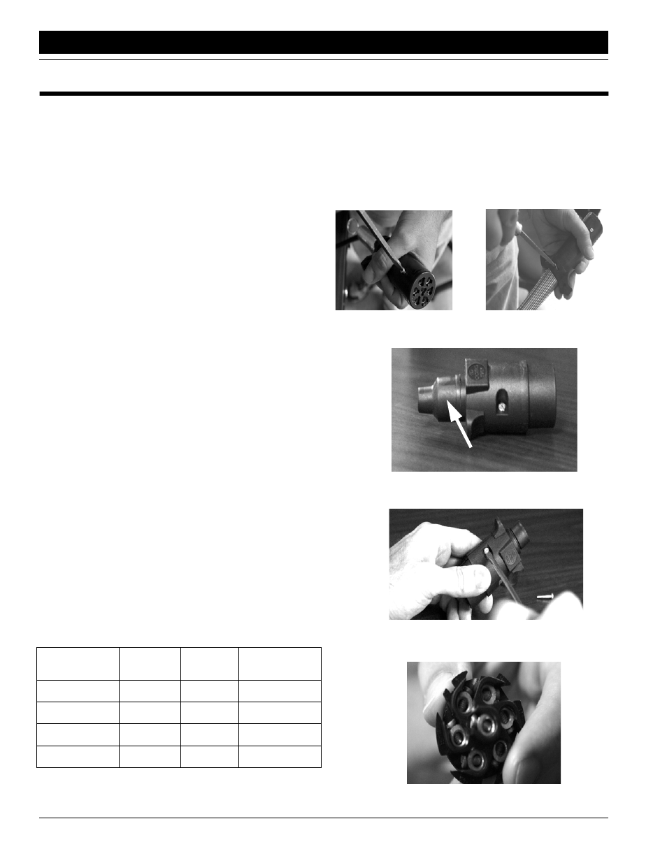
Wiring Drill
NOTE: If tractor does not comply with ASAE connector, use
the European adapter.
Refer to Figure 1-1
1.
Remove screw from outer casing of ASAE connector.
2.
Loosen screw holding wires in place from outer casing of
ASAE connector. Pull outer casing apart. Disconnect
wires from connector by removing screws.
3.
Completely remove outer casing from wires.
Refer to Figure 1-2
4.
Remove black rubber end piece from European adapter.
Thread wires through black rubber end piece starting with
the smaller end.
Refer to Figure 1-3
5.
Remove the two screws holding the outer casing of the
European adapter together. Keep for reuse.
6.
Remove connector from outer casing. Thread wires un-
der metal bar in bottom of outer casing.
Refer to Figure 1-4
7.
Attach wires to connector using the terminal number indi-
cators on the back of the connector and the table below.
8.
Align connector in bottom of outer casing.
Conductor
Identification
Wire
Color
Terminal
Number
Circuit
Wht
White
3
Ground
Yel
Yellow
1
Left Blinker
Grn
Green
4
Right Blinker
Brn
Brown
6
Tail Lamps
NOTE: BE SURE CONNECTOR AND CASING ARE
PROPERLY ALIGNED, OTHERWISE CASING WILL NOT
FIT CORRECTLY.
9.
Tighten screws securing wires and metal bar in place.
10. Replace top of outer casing. Insert and tighten screws
removed in Step 3.
11. Slide black rubber end piece over the end of the outer
casing securing wires.
23264
Figure 1-1
Removing ASAE Connector
Figure 1-2
European Adapter
23254
Figure 1-3
Remove Screws to Outer Casing
Figure 1-4
Back of Connector
23265
23255