Great Plains CTA4000 Quick Start User Manual
Quick setup guide for intelliag model cta
11001-1459C-201107
©2011 DICKEY-john Corporation
Specifi cations subject to change without notice.
Quick Setup Guide for IntelliAg Model CTA
STEP 1: Pre-Programming Preparation:
Power on vehicle via ignition switch to activate Virtual Terminal (VT). Main menu will display pre-programmed default settings.
If errors are detected (e.g., failed sensors, incorrect confi guration) an alarm and code will display. Alarms are silenced by pressing the Alarm Cancel button
. Refer to Operator’s
manual for troubleshooting assistance.
The system has three user levels. The system loads in user level 1 (operator level) at every power cycle. Access to user level 2 and 3 screens to setup constants (system confi guration)
requires a password available through an authorized Great Plains dealer.
1.
2.
3.
The Quick Setup Guide assumes the Virtual Terminal, Working Set Master Module, Working Set Member Module, and all sensors
have been connected and properly installed. Quick Setup Guide assumes channel 1 (front bin) to be seed and channel 2 (rear
bin) to be fertilizer. Reference the Operator’s manual for installation instructions.
STEP 3: Auto Confi guration (identifi es sensors connected to each module)
Auto confi g is performed at the factory, but may need to be done in the fi eld as changes
are made to the system or if options are added to the base system.
Verify Auto Confi g results are correct. Check that the correct number of rows are assigned to
the correct module and number of hoppers and pressure sensors are assigned accurately.
To Run Auto Confi g:
Press Next Page
until Module Confi guration button appears.
Press Module Confi guration button
.
Press AUTO CONFIG button
.
Hour glass will indicate system is detecting the presence of seed, pressure, or hopper
sensors connected to each module and automatically assigns to the appropriate module.
When Auto Confi g completes, press the Row Assign button
to display the Row
Assignment screen to verify correct Row # is assigned to the correct module based on serial
number.
Enter # of rows assigned to each module.
1.
1.
2.
3.
4.
5.
6.
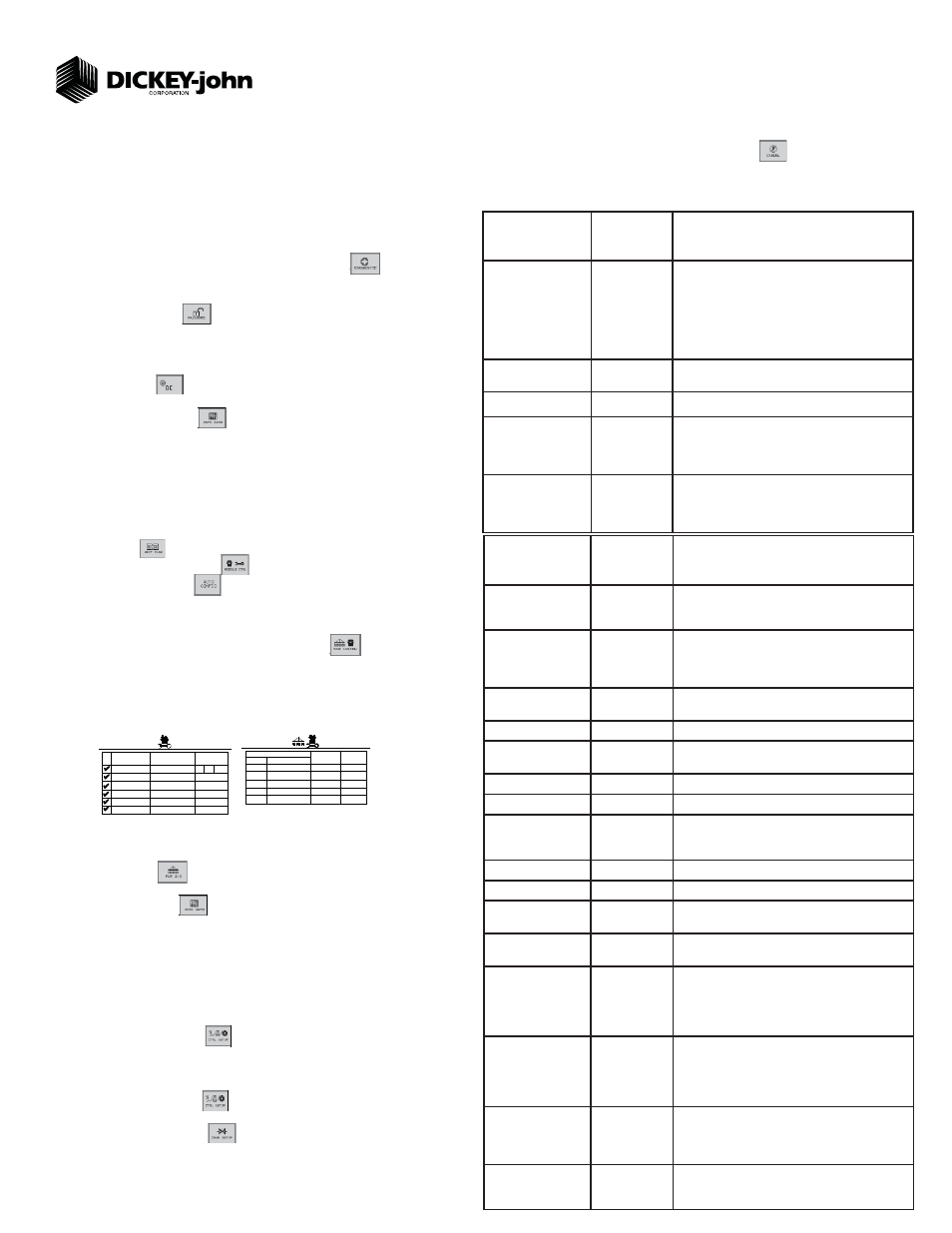
STEP 5A: Material Confi guration Setup (Granular Seed Monitor)
16 different materials can be confi gured as seeding and fertilizer controls. Material defaults on
the Control Setup screen are Seed 1-4 (Granular Seed Control) Seed 5-8 (Granular Seed
Monitor) Fert 1-4 (Granular Fertilizer Control) Fert 5-8 (Granular Fertilizer Monitor).
Reference the System Confi guration section in the Operator’s Manual for additional setup
instructions.
Press the Control Setup button
.
At the Control Setup screen, select one of the 16 material buttons to edit (labeled Seed 1-8
and Fert 1-8).
Enter desired values from Table B.
Press the Control Setup button
to return to the Control Setup screen.
Repeat steps 2-4 for additional materials.
Press the Channel Setup button
to enter channel setup constants.
1.
2.
3.
4.
5.
6.
TABLE B:
Gran Seed Mon
Material Setup
Default Value/
Value to Enter Instructions/Defi nitions
Matrl Label
Seed 5
Material Name can be customized to accurately defi ne
the material’s type. Creating a name allows for quick
identifi cation at the Control Setup screen.
Type
Gran Seed
Monitor
Desired type of application control channel being used
for a specifi c material. The Material Type must correctly
match the Control Type to be able to select material from
the Control Setup screen and operate properly.
Display Units
Lbs/Ac
Displays primary and secondary readout units in Lbs/Ac
or Kg/ha.
Target Rate
60 lbs
Desired rate of application in lbs/Ac.
Density
60 lbs/bu
Establishes the density of material. Density units can be
entered in lbs/bu or lbs/ft
3
.
# of Towers
5
Establishes the number of towers for that channel.
Calibration Constant
77600 Pul/Ft
3
Number of pulses to drop 1 cubic foot/liter of material.
Variable Cal Constant
Disabled
Adjusts the accuracy of the seed amount dispensed
based on the seed type. A selection of 25 pre-defi ned
seed types are available.
Low Shaft RPM
1
Set to desired min seed meter RPM.
High Shaft RPM
50
Set to desired max seed meter RPM.
Prod Level Alarm
0
Sets the weight to trigger alarm indicating low seed levels
in lbs.
Seeds per Pound/Kg
3000 Lb
Converts the current application rate from Lb/ac to KS/Ac
to determine population and population alarms.
High Pop Alarm
20%
This is the percentage above the target population of
the seeder channel if rows are assigned to the seeder
channel. If rows are not assigned to a seeder, this is
the percentage above average seeder population for all
unassigned rows.
Low Pop Alarm
20%
This is the percentage below the target population of the
seeder channel if rows are assigned to the seeder chan-
nel. If rows are not assigned to a seeder channel, this is
the percentage below average seeder population for all
unassigned rows.
On/Off Pattern
Every Row On
On/Off Pattern indicates specifi c row patterns to be on
or off. Select pre-defi ned seeder All Row On pattern.
For other pre-defi ned seeder patterns or individual row
settings, reference Operator’s manual.
Row Fail Rate
2/1
Sets the threshold for row failure alarms. Entered in
seeds per second. 2/1 is a row failure threshold of 2
seeds in 1 second.
STEP 4: Row Status/Row Width Setup
Press Row I/O button
.
Enter desired values using Table A as reference.
Press Work Screen button
to return to the Main Work screen.
1.
2.
3.
1
# O F
R O W S
MODULE
ADDR.
TYPE
R O W
# ’ s
1 - 1 0
WSMB-18R
1 0
Seed Sensor Configuration Screen
11 - 2 0
S E R I A L
N U M B E R
1
M O D U L E
T Y P E
M O D U L E
A D D R .
WSMB-18R
WSMT-ACCGP
2
10001
10003
WSMB-18R
3
3
WSMB-18R
4
2 1 - 3 0
10004
WSMB-18R
4
10002
Module Configuration Screen
10005
10006
WSMB-18R
WSMB-18R
6
5
5
WSMB-18R
WSMB-18R
WSMB-18R
1 0
1 0
1 0
3 1 - 4 0
4 1 - 5 0
1 0
6
2
Above screens depict setup for 50 row.
For 65 row (# of Rows = 13)
For 80 row (# of Rows = 16)
TABLE A: Row
Status/Row Width
Setup
Default Value/
Value to Enter Instructions/Defi nitions
Row Width
(50 row)
10
Enter row width distance in inches to calculate seed rate
data.
Row Width
(65 row)
7.5
Row Width
(80 row)
6.0
Auto Update Width
Disabled
When enabled, implement width will automatically calcu-
late. If disabled, manually enter implement width.
Implement Width
480
Manually enter implement width in inches.
On/Off Pattern
Every row on
On/Off Pattern indicates specifi c row patterns to be on
or off. Select pre-defi ned seeder All Row On pattern.
For other pre-defi ned seeder patterns or individual row
settings, reference Operator’s Manual.
Pop/Block Pattern
Every row
blockage
Determines which sensors are used to calculate popul-
tion and those used only for blockage detection. Select
pre-defi ned Every Row Blockage. For other pre-defi ned
patterns, reference Operator’s Manual.
Proceed to Step 5C if a variable rate kit is installed.
STEP 2: Change User Level to Dealer Level
To change the user level, a 6-digit password is required. Password includes the fi ve-digit
serial number found on the label of the working set master or Information screen.
On the IntelliAg Main Work screen, press the Diagnostics button
.
At the Diagnostics screen, press the Information button
At the Information screen, record serial number of WSMT.
Press the Password button
.
On the Password screen, enter the 6-digit password as follows: enter the fi rst digit as 2 for
User Level 2. For the next fi ve digits, enter the Working Set Master serial number taken from
the WSMT or Information screen.
Press the OK button . “Dealer screens on” appears at the bottom of screen confi rming
the password and dealer screens are activated.
Press the Work Screen button to return to the Main Work screen.
1.
2.
3.
4.
5.
6.
7.