Great Plains Disk Harrow Update Gauge Wheel User Manual
Page 2
2
Disk Guage Wheel Update
Great Plains Manufacturing, Inc.
558-185M
08/23/2010
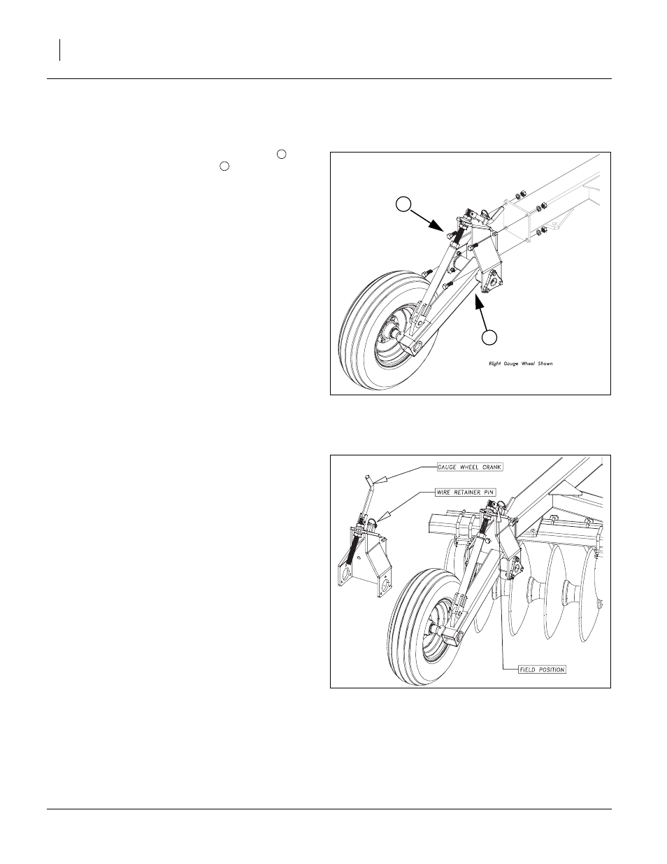
Refer to Figure 3
Note: There is a RH (right hand) and LH (left hand)
assembly. The RH is shown.
4.
Now the 556-220K gauge wheel assembly
may be
installed using the 3/4 x 2 hex bolts
, 3/4 lock washers
and 3/4 nuts.
5.
Torque the bolts to 265 ft-lb.
6.
Repeat the same procedure for the left hand side.
To change the gauge wheel setting, remove the wire
retaining pin and fold gauge wheel crank up to adjust.
Lower or raise the gauge wheel by turning the gauge
wheel crank. Raise the wheels up until you have the disk
adjusted in the fore-and-aft, side to side and the desired
working depth you desire. Fold the gauge wheel crank
back down in the field position and reinstall the wire retain-
ing pin. As you are running the disk through the field, stop
the tractor leaving the disk in the ground. Now you can
adjust the gauge wheels 1/2” to 1-1/2” above the ground.
After initial adjustment you can turn gauge wheel crank the
same amount as the depth stop crank (if changed, but
crank turns opposite way than depth control crank to keep
initial setting). This position should be maintained to pre-
vent excessive wear to gauge wheel parts.
FigureSpacer:
Figure 3
Gauge Wheel Assembly
41868
2
1
1
2
FigureSpacer:
Figure 4
Gauge Wheel Adjustment
41870