Speed sensor – Great Plains 3N-30P SE Assembly Instructions User Manual
Page 8
196-304m
10/7/2004
Great Plains Mfg., Inc.
Monitor System Option
8
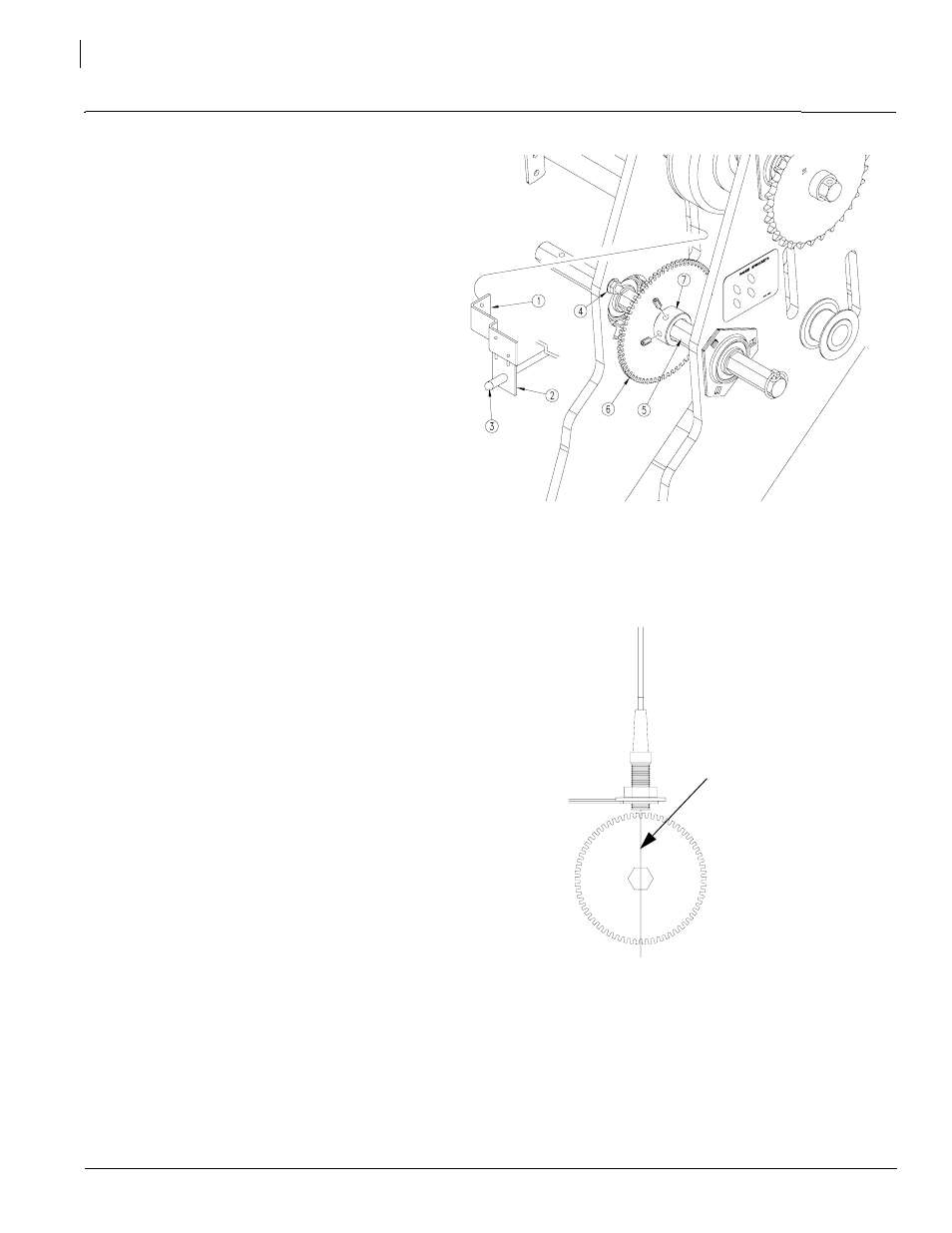
Refer to Figure 10
1.
Assemble mounting bracket (1) and sensor
bracket (2) together using hardware supplied
in kit. Assemble mounting bracket to the in-
side of the plate on the left gauge wheel. In-
stall the Dickey-john magnetic pickup sensor
(3) to the sensor mounting bracket.
2.
Loosen fasteners at bearings (4) on either
side of the contact wheel pivot shaft (5). Slide
pickup disk (6) onto shaft using lock collars (7)
on either side to hold in place. Tighten bear-
ings back down.
Refer to Figure 11
3.
Align sensor and pickup disk with centerline.
Be sure to tighten set screws in the lock col-
lars after alignment is done.
4.
Connect sensor to wire harness sensor ex-
tension.
5.
Set initial distance between sensor and pick-
up disk at 0.040 inch. This may need to be ad-
justed up or down as necessary.
6.
Route the wire harness along the tongue to
the tractor. The sensor is connected to the 2-
pin connector on the cab harness at the hitch.
Refer to the DICKEY-john Installation and Operat-
ing Manual for further instructions.
19286
Figure 10
Mounting Bracket
Centerline
Figure 11
Sensor
Speed Sensor