Great Plains 3N-30P SE Assembly Instructions User Manual
Page 4
196-304m
10/7/2004
Great Plains Mfg., Inc.
Monitor System Option
4
Assembly Instructions for 196-301A 10 inch Row Spacing
Refer to Figures 4 and 5
1.
Mount one each of the material flow modules to the
wing frame as shown in figure 1. Mount two each, of the
material flow modules, on the right-hand and left-hand
side of the center frame using 1/4" x 1 1/2" bolts and
1/4" lock nuts as shown.
NOTE
:
If there are no predrilled holes in the frame use the
templates provided, mark and drill 5/16” holes for mounting
modules. (Template is on pages 9 & 10)
2.
Place the harness wire bundle on the frame by the ma-
terial flow module. Connect the wire extensions to the
openers starting at the left side of the drill in numerical
order. Wire extension number 1 with first opener on the
left. Continue in the same manner until all wire exten-
sions are connected. Fasten the harness to the frame
with cable ties.
3.
Connect black and gray colored leads into the material
flow modules. Inlets are color coded. Black to black and
gray to gray.
Refer to Figure 6
4.
Attach sensor lead marked IN from the left-hand wing
frame harness to the 15’ smart sensor extension wire.
Route the 15’ extension using the same path as the
opener lift hoses allowing the same slack at the drill
toolbar pivots as the other hoses. Connect this exten-
sion to the center frame harness lead marked OUT.
Use cable ties to secure the wires in place. Mark these
extensions P-1, left-hand and P-2, right-hand for fur-
ther reference. Put a cable plug in the OUT lead of the
left-hand frame harness.
5.
Attach sensor lead marked IN from the center frame
harness to the 30’ smart sensor extension wire. Route
the 30’ extension using the same path as the opener lift
hoses allowing the same slack at the drill toolbar pivots
as the other hoses. Connect this extension to the right-
hand wing frame harness lead marked OUT. Use ties
to secure the wires in place.
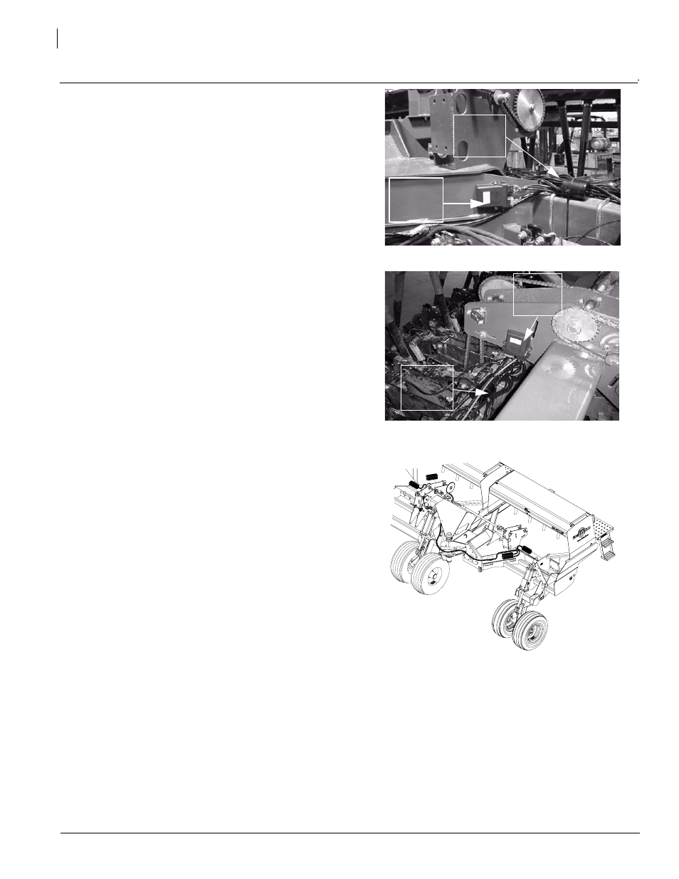
6.
Attach a 40’ extension to the IN from the right-hand
wing frame harness and route it back to the center
frame and through the tongue tube to the tractor once
again using the same routing as the hydraulic hoses
and allowing the same slack. It is connected to the P1
port of the cab harness at the tractor hitch. Put a cable
plug in the P2 port of the cab harness.
NOTE: Left-hand side of drill is shown in figures. Left-hand
and Right-hand sides on the Drill are done in the same
manner. The left side will go to port 1 and the right side to
port 2.
7.
Refer to page 5 for a detailed listing of parts and sche-
matics for this particular monitor system.
19217
Harness
Wire
Bundle
Figure 6
Routing for wire Harness
19255
Figure 5
Center Drive System Frame
Figure 4
Wing Frame
19218
Material
Flow
Module
Material
Flow
Module
Harness
Wire
Bundle
8.
For console assembly, speed sensor and
other schematics illustrations refer to the
DJ manual found in the monitor system
package.
9.
Refer to page 8 for speed sensor instruc-
tions if sensor is being used.
NOTE: J1 accessory harness and 40’ extension
is not used if speed sensor on drills is not used.