Great Plains 2020P Assembly Instructions User Manual
General information assembly instructions, Marker option, Marker assembly
© Copyright 2000 Printed
Great Plains Mfg., Inc.
Used with:
Installation Instructions
113-688M
3-Point Precision Seeding System
Marker Option
• 1510P and 1520P
• 2010P and 2020P
General Information
Assembly Instructions
When you see this symbol, the subsequent instructions and
warnings are serious - follow without exception. Your life and
the lives of others depend on it!
!!
These instructions explain how to install the Mark-
er Option on the 15 and 20 foot 3-point Precision
Seeding Systems.
The markers fold and unfold hydraulically for field
operation. The marker disks leave a line for the
drill operator to follow on the next field pass. Mark-
ers are mounted on the drill frame and require two
hydraulic remote valves on the tractor. A se-
quence valve is available so markers can be
operated on one hydraulic circuit.
These instructions apply to:
113-691A
15P Single LH Marker Package
113-692A
15P Dual Marker Package
113-693A
20P Single LH Marker Package
113-694A
20P Dual Marker Package
Marker Assembly
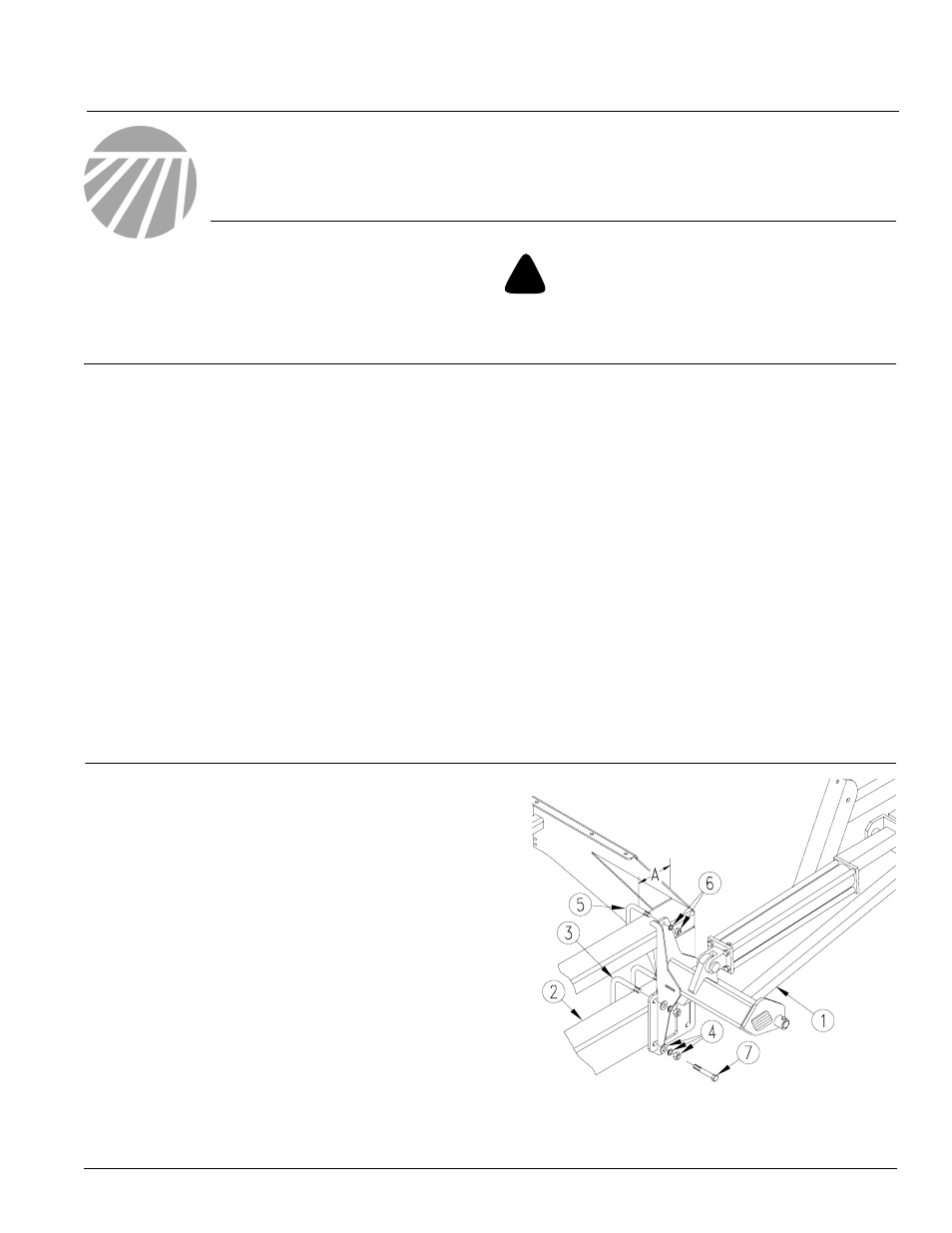
Figure 1
First Marker Section Assembly
18413
15 foot A = 7 3/8 inches
20 foot A - 6 1/2 inches
.
1.
Lower drill into field position. Allow 9 feet on
each end of a 15-foot drill and 11 feet on each
end of a 20-foot drill for marker assembly.
2.
Mount first marker section (1) on drill 7 x 5
inch frame tube (2). Mount marker at the end of
the drill using dimension "A" as a starting point.
Some row spacings will require the mount to
be adjusted in or out from this starting point.
3.
Secure marker section with 5/8 inch u-bolts
(3), lock washers, washers and nuts (4). and
1/2 inch u-bolts (5), lock washers and nuts (6).
NOTE: On the 20-foot drill with 15 inch row spac-
ing, the last opener is bolted to the marker mount
using 5/8 x 6 1/2 inch straight bolts (7).
Manual Update
Refer to the 3-Point Precision Seeding System
operator’s manual for detailed information on
safely operating, adjusting, troubleshooting and
maintaining the Marker Option. Refer to the parts
manual for part identification.
118-732M
1510P and 1520P Operator’s
Manual
118-732P
1510P and 1520P Parts Manual
118-740M
2010P and 2020P Operator’s
Manual
118-740P
2010P and 2020P Parts Manual
Before You Start
Page 7 is a detailed listing of parts included in the
Marker Option package. Use this list to inventory
parts received.
1/3/2000