Great Plains 2000 Predelivery Manual User Manual
Page 7
5
Section 1 Assembly
12/28/05
12, 15 and 20 Series 3-Point Drills 118-390M
Great Plains Mfg., Inc.
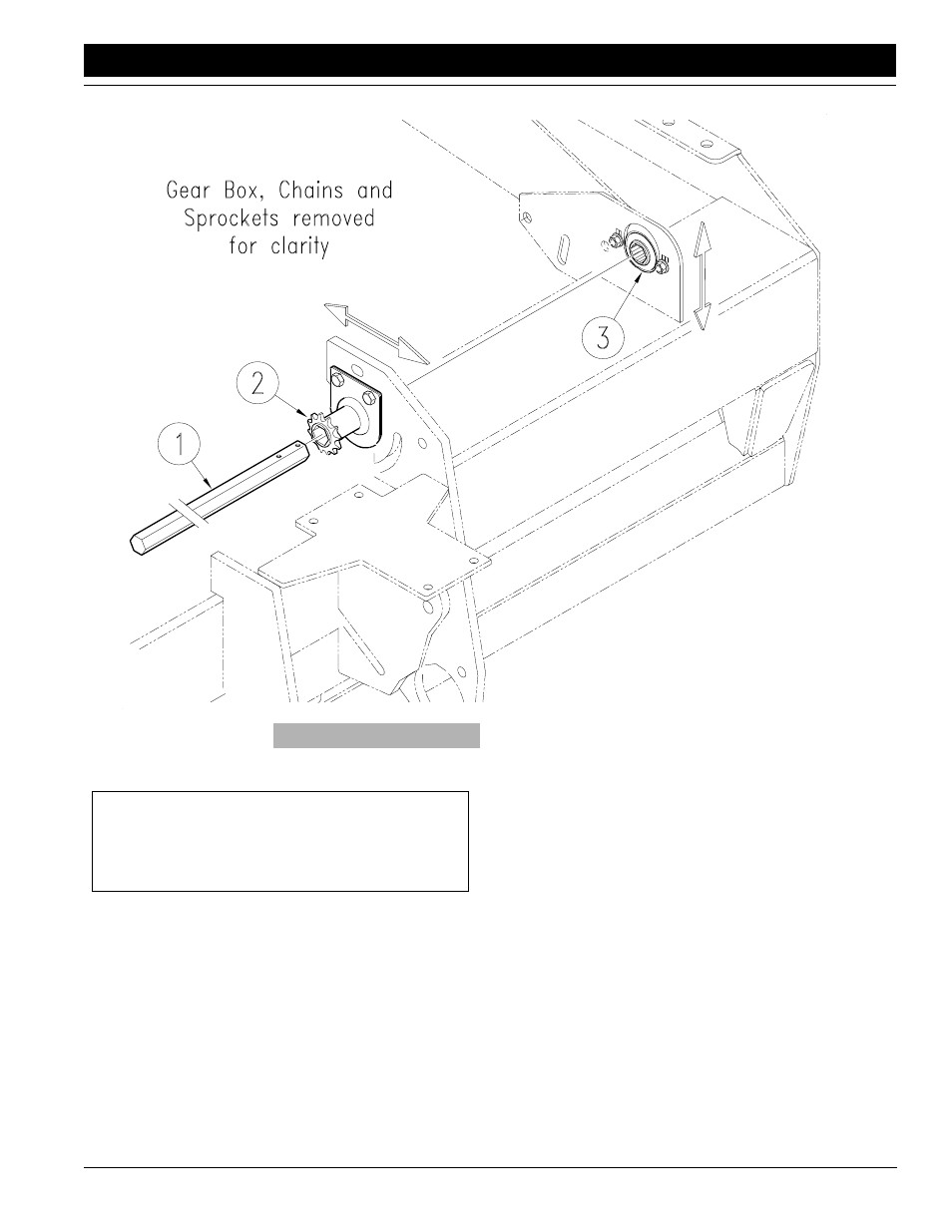
Figure 1-2
Install Drive System
NOTE: If using the 15-foot drill with an All Seeds Hitch, the
extended wing (2) must be mounted to the inside of the
drill. Order Great Plains part number 120-210H to com-
plete installation.
3.
Check dimension A for the right-hand gauge wheel
and reposition if necessary using the same proce-
dure.
4.
Jack up or otherwise support gauge-wheel arms.
Mount tires on wheel hubs. Tighten nuts as specified
on Torque Valves Chart, “Appendix,” page 9.
Refer to Figure 1-2.
1.
Locate the 7/8-inch, hex jackshaft (1).
2.
Starting at the gauge wheel, slide the shaft through
the 12-tooth sprocket and bearing assembly (2). If the
shaft aligns itself with the 7/8-inch, hex-bore bearing
(3), the sprocket and bearing assemblies are properly
in place.
•
If the shaft is too high or low to enter bearing (3), loos-
en the flangette bolts and slide bearing (3) up or down
until the height matches the shaft.
•
If the shaft is too far forward or back to enter bearing
(3), slide the sprocket and bearing assembly (2) in its
mounting holes on the gauge wheel until shaft easily
slips into the bearing mounted on the drill frame.
3.
Tighten both sets of bearing bolts.
IMPORTANT: Note the extended wing (2) on top of
the left-hand, gauge-wheel mount where the jack-
shaft bearing is mounted. Mount this wing toward the
outside on 15- and 20-foot drills and toward the inside
of 12-foot drills.
12-Foot with Single Gauge Wheels
5 3/4 inches
12147