Danger, Position gauge wheels – Great Plains 2000 Predelivery Manual User Manual
Page 6
4
Section 1 Assembly
12, 15 and 20 Series 3-Point Drills 118-390M
12/28/05
Great Plains Mfg., Inc.
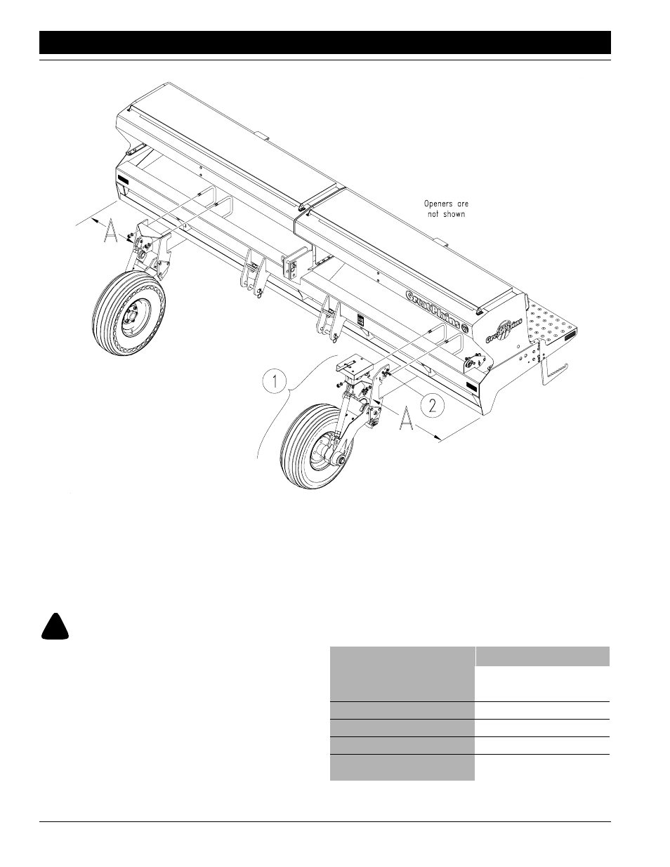
Position Gauge Wheels
Gauge-wheel arms are factory-mounted on the drill frame.
Follow these steps to reposition the gauge wheels to the
proper width for your drill application.
!
DANGER!
Crushing hazard. You may be severely injured or killed by the
drill if it falls or tips forward. Securely support the drill with
jack stands or blocks before installing the gauge wheels.
Refer to Figure 1-1.
1.
Block up or otherwise support the front of the drill to
keep it from tipping forward.
2.
Measure dimension A for the left-hand gauge wheel
(1) as shown in Figure 1-1. Refer to the following chart
for gauge-wheel placement. If necessary, mark the
main frame where you will remount the wheel.
Figure 1-1
Mount Gauge Wheel On Frame
12146
To reposition the arm, use mechanical assistance to lift
and support the arm. Remove the two u-bolts, lift the
gauge-wheel arm, and reposition it on the frame. Install
the two U-bolts from the back side of the frame tube
and through the mounting holes. Secure with lock
washers and nuts.
Gauge Wheel Placement Chart
Drill Description
15- and 20-Foot with Single or Dual
Gauge Wheels, Standard Installa-
tion
15 1/2 inches
20-Foot with 30-Inch Irrigation Beds
15 1/2 inches
20-Foot with 36-Inch Irrigation Beds
15 3/8 inches
20-Foot with 40-Inch Irrigation Beds
25 1/2 inches
15-Foot with Single Wheel, Outside
Mount (See NOTE below)
13 1/4 inches