Install casters, Install lock out plunger, Install lock tube – Great Plains 3P1006NT Assembly Instructions User Manual
Page 7
Install Casters
Great Plains Manufacturing, Inc.
7
05/05/2011
151-181M
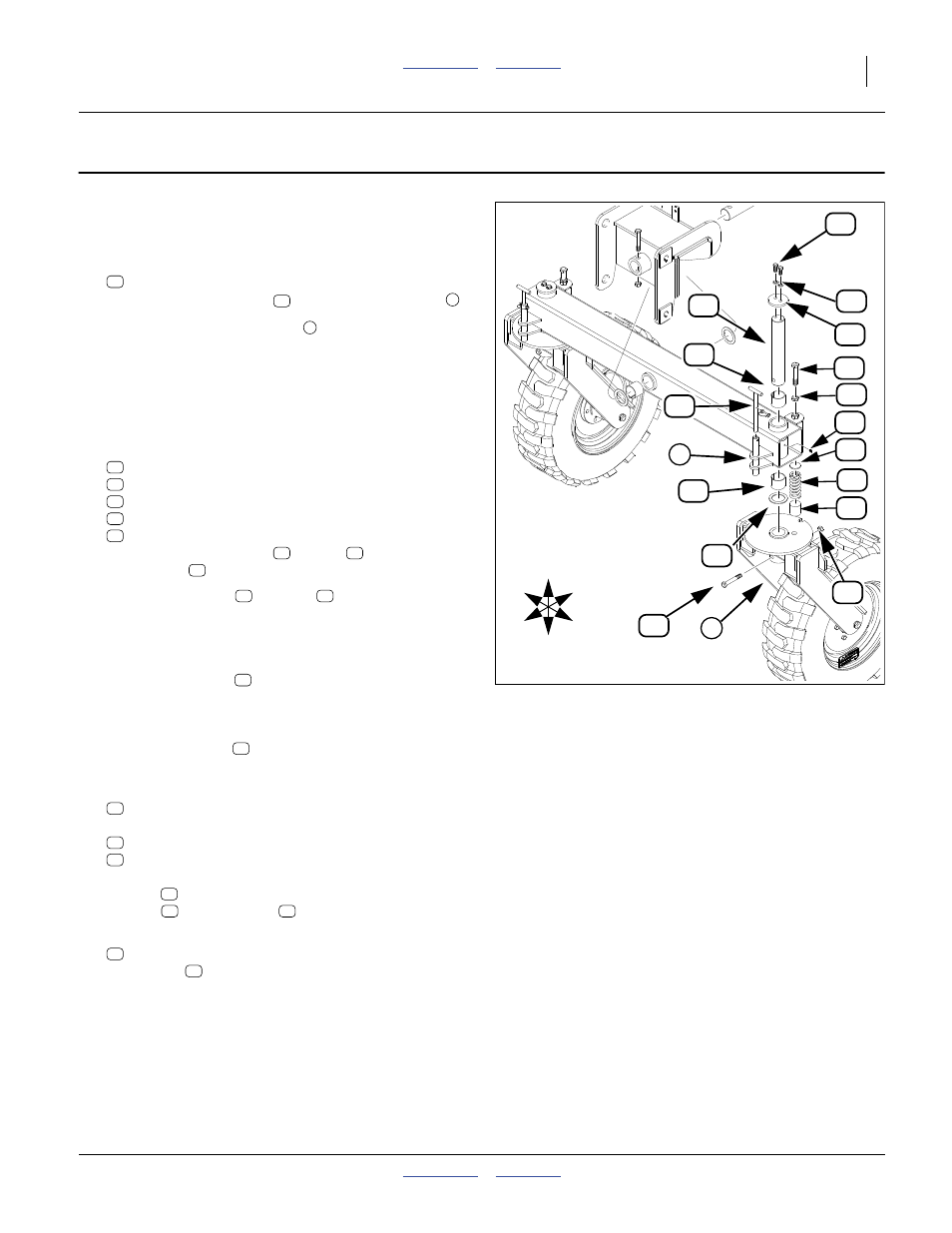
Install Casters
Install Lock Out Plunger
22. Select one each:
Insert transport lock pin
in top of plunger tube
.
Note: The lock out plunger tube
MUST be facing to
the front of the drill. If it is facing to the rear, the
pivot arm tube is on backwards and must be
switched.
Install Lock Tube
23. Select one each:
266-020D UHMW RND 2.0 DIA X 2.0 LONG
807-143C SPRING COMP 1.88OD x .362W
266-012D PLATE RND 3/16" THK 1 7/8" DIA
802-067C HHCS 3/4-10X4 GR5 FTHD
803-048C NUT HEX JAM 3/4-10 PLT
Assemble UHMW block
, spring
round plate
. Push up inside lock tube.
24. Complete with nut
“Caster Brake Adjustment” on page 8.
Install Casters
25. Place caster shaft
up through new update caster
arm tube.
If bushings are not already in arm, using a mallet,
drive one bushing
into shaft hole on arm tube bot-
tom and one in top hole of arm tube.
26. Select saved caster cap:
and saved bolts and washers, two each:
802-034C HHCS 1/2-13X1 1/4 GR5
804-015C WASHER LOCK SPRING 1/2 PLT
Complete assembling shaft by placing caster retain-
ing cap
on top and securing with two washer lock
springs
and two bolts
27. Select one:
800-001C GREASE ZERK STRAIGHT 1/4-28
Install zerk
in shaft at end of pivot arm tube.
28. Repeat same steps for other caster.
Figure 8
Caster Shaft Installation
32133
2
U
D
F
B
L
R
1
2
2