Great Plains AS PTO Pumps User Manual
General information, Assembly instructions, Pto sprayer pump
1
Installation Instructions
Great Plains Mfg., Inc.
© Copyright 1998 Printed 4/8/04
Used with:
•
•
507-095M
Application Systems
PTO Sprayer Pump
3P300
TA500
General Information
These instructions explain how to install the Application Systems
PTO pump. The pump pressurizes sprayer contents for applica-
tion.
These instructions apply to:
507-041A
PUMP TA 540 DRIVE SHAFT ASSY
507-042A
PUMP TA 1000 1 3/8 DRV SHAFT
507-051A
PUMP 3-POINT 540 ASSY
507-052A
PUMP 3-POINT 1000 1-3/8 ASSY
Manual Update
Refer to the operator’s manual for detailed information on safely
operating, adjusting, troubleshooting and maintaining the Appli-
cation Systems PTO pump. Refer to the parts manual for part
identification.
• 3P300 Operator’s Manual . . . . . . . . . . . . . . . . . . .500-103M
• 3P300 Parts Manual. . . . . . . . . . . . . . . . . . . . . . . . 500-062P
• TA500 Operator’s Manual. . . . . . . . . . . . . . . . . . . .500-102M
• TA500 Parts Manual. . . . . . . . . . . . . . . . . . . . . . . . 500-061P
Before You Start
Beginning on page 3 are detailed listings of parts included in the
Application Systems PTO pump packages. Use these lists to in-
ventory parts received.
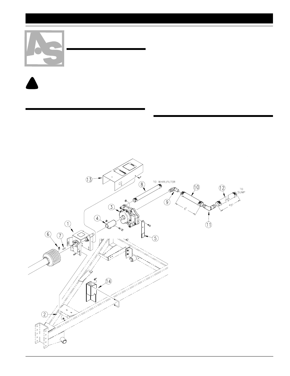
Assembly Instructions
TA500 Assembly
1.
Attach driveline-bearing mount (1) to sprayer tongue (2) us-
ing 3/8-inch bolts and flange nuts.
2.
Mount pump (3) onto output shaft of driveline-bearing
mount. Secure shaft coupler (4) with 1/2-inch bolts and ny-
lock nuts.
3.
Mount torque arm (5) on pump using 5/16-inch car-
riage bolts and flange nuts.
4.
Thread set screws (6) into yoke of PTO shaft and
install key (7) into input shaft of bearing mount.
Slide PTO shaft onto
input
shaft and
tighten
set screws.
5.
Install 1-
inch hose (8)
between pump
outlet and Whirlfilter
inlet. Secure with worm
clamps.
6.
Cut 1 1/2-inch hose into a 6-
inch-long section and a 45-
inch-long section.
7.
Using 1 1/4-by-1 1/2-inch elbow (9), install 6-inch
section of hose (10) onto pump inlet. Install 1 1/2-
inch elbow (11) in other end of 6-inch section. Se-
cure with worm clamps.
8.
Install 45-inch section of hose (12) between elbow
and tee prior to Quick-Fill inlet under sprayer tank.
Secure with worm clamps.
9.
Mount driveline shield (13) onto driveline-bearing
mount using 5/16-inch flange bolts.
10. Mount torque-arm stop (14) onto left side of tongue
using u-bolt and flange nuts. Adjust stop to line up
with torque arm.
11. Tighten all hardware and clamps. Refer to opera-
tor’s manual for setup and operating instructions.
Figure 1
TA500 Assembly
17392
When you see this symbol, the subsequent instructions and
warnings are serious - follow without exception. Your life and
the lives of others depend on it!
!!
■