Gauge wheel adjustment, Thread protectors, Gauge wheel adjustment thread protectors – Great Plains 4336 DH Operator Manual User Manual
Page 28
24
3323-4336DH
Great Plains Manufacturing, Inc.
556-100M
05/22/2012
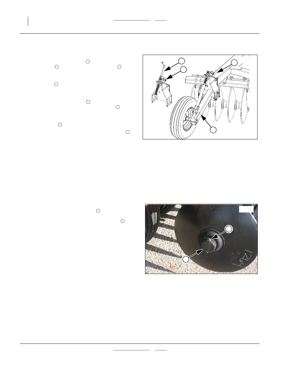
Gauge Wheel Adjustment
Refer to Figure 19
7.
To change the gauge wheel
setting, remove the wire
retaining pin
and fold gauge wheel crank
up to
adjust.
8.
Lower or raise the gauge wheel by turning the gauge
wheel crank
. Raise the gauge wheels up until the
disk is adjusted in the fore-and-aft, side-to-side and to
the desired working depth you desire.
9.
Fold the gauge wheel crank
back down in the field
position and reinstall the wire retaining pin
.
10. As you are running the disk through the field, stop the
tractor leaving the disk in the ground. Now adjust the
gauge wheels
1/2” to 1 1/2” above the ground.
11. After initial adjustment, turn gauge wheel crank
the
same amount as the depth stop crank (if changed, but
crank turns opposite way than depth stop crank to keep
initial setting).
12. This position should be maintained to prevent exces-
sive wear to gauge wheel parts.
Note: Tractor Speed: The ideal working speed for the disk
harrow is 5 to 6 mph. Working too slow may cause
plugging, poor incorporation or mixing of crop residue
and reduced weed kill. Running too fast may cause
streaks in chemical incorporation and ridging.
Thread Protectors
Refer to Figure 20
13. Make sure thread protector bolts
are in place and
tight. Gang bolt thread damage may occur at hinge
point when gangs flex without protector caps
. Lost
caps with no bolt may allow gang nut to become loose.
Figure 19
Gauge Wheel
41619
3
1
2
4
1
2
3
3
4
2
1
3
Figure 20
Thread Protector
42126
1
2
1
2