Hydraulics assembly – Great Plains 4000-3S Assembly Instructions User Manual
Page 7
2/28/2006
113-728M
Great Plains Mfg., Inc.
7
Installation Instructions
10. Lay hoses flat along tool bars. Tie hoses down with
plastic cable ties to prevent pinching or kinking
during folding.
11. Proceed with "Bleeding Marker Hydraulics", page
Single Marker With Selector Valve
Refer to Figure 10
1.
Mount selector valve (1) to valve mounting plate (2)
with 3/8" x 3 1/4" bolts (3), 3/8" lock washers (4) and
3/8" nuts (5).
Refer to Figure 11 on page 8
2.
Install elbow fittings (6) in cylinder ports.
3.
At rod end of marker cylinder, install a 3/8" MNPT
adaptor (7) into elbow fitting. Install a needle valve
(8) into adaptor and a 3/8" MNPT x 9/16" MJIC adap-
tor (9) into the needle valve.
4.
Assemble 270" hose (10) to base end elbow fitting
and 277" hose (11) to rod end elbow fitting.
5.
Route hoses through marker carrier mount at cutout.
Then route the hoses along the same path as opener
lift hoses, allowing the same slack at drill toolbar piv-
ots.
6.
Attach adapters (12) to hoses (10 & 11). Assemble the
408" long hoses (13) to adapters.
7.
Attach adapters (14) to front and rear ports, and el-
bows (15) to cross ports of selector valve (1).
8.
Assemble hoses (13) to rear ports of selector valve.
Assemble hoses (16) from fold cylinders to front
ports of selector valve.
9.
Assemble hoses (17) to elbows (15) on selector valve.
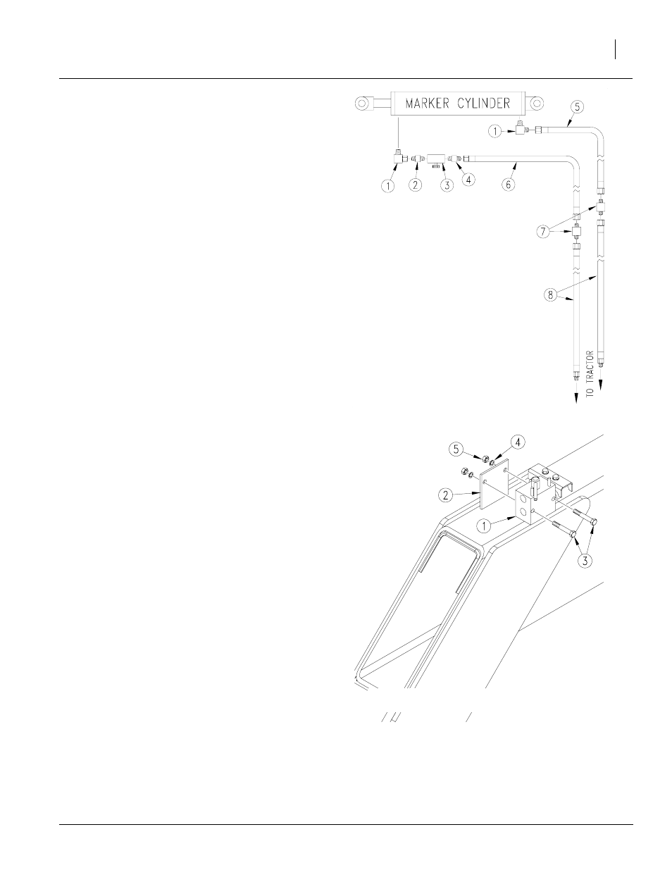
Hydraulics Assembly
Single Marker
Refer to Figure 9
1.
Install elbow fittings (1) in cylinder ports.
2.
At rod end of each cylinder, install a 3/8" MNPT
adaptor (2) into elbow fitting. Install a needle valve
(3) into adaptor and a 3/8" MNPT x 9/16" MJIC adap-
tor (4) into the needle valve.
3.
Assemble 270" hose (5) to base end elbow fitting
and 290" hose (6) to rod end elbow fitting.
4.
Route hoses through marker carrier mount at cut-
out. Then route the hoses along the same path as
opener lift hoses, allowing the same slack at drill
toolbar pivots.
5.
Assemble 9/16" MJIC adapters (7) to hoses (5 & 6).
Assemble the 408" long hoses (8) to adapters.
6.
Lay hoses flat along tool bars. Tie hoses down with
plastic cable ties to prevent pinching or kinking dur-
ing folding.
7.
Proceed with "Bleeding Marker Hydraulics", page
11.
Figure 9
Single Marker Hydraulics
18935
Figure 10
Selector Valve Mounting
18937