Great Plains 4000-3S Assembly Instructions User Manual
General information assembly instructions, Marker option, Manual information
© Copyright 2000 Printed
Great Plains Mfg., Inc.
Used with:
Installation Instructions
113-728M
4000-3S
Marker Option
• 4000-3S 40’ 3-Section Drill
General Information
Assembly Instructions
When you see this symbol, the subsequent instructions and
warnings are serious - follow without exception. Your life and
the lives of others depend on it!
!!
These instructions explain how to install the marker
option. The markers fold and unfold hydraulically for
field operation. The marker disk leaves a line for the
drill operator to follow on the next field pass. Markers
are mounted on the drill frame and require two hy-
draulic remote valves on the tractor. A sequence
valve is available so markers can be operated on one
hydraulic circuit.
These instructions apply to:
113-708A
4000-3S Single Marker Bundle
113-707A
4000-3S Dual Marker Bundle
113-048A
3S-4000 RH Marker Package
2/28/2006
Manual Information
Refer to the 4000-3S operator’s manual for detailed
information on safely operating, adjusting, trouble-
shooting and maintaining the marker option. Refer
to the parts manual for part identification.
195-242M
4000-3S Operator’s Manual
195-242P
4000-3S Parts Manual
Before You Start
Beginning on page 12 is a detailed listing of parts in-
cluded in the marker option package. Use this list to
inventory parts received.
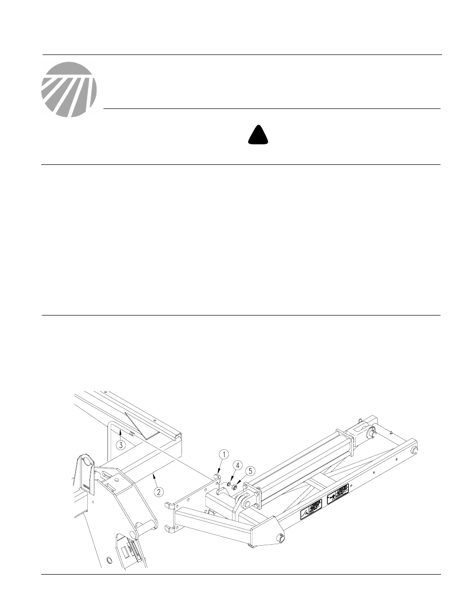
2.
Mount first marker section (1) on drill frame tube
(2) as shown. Secure with four 5/8" x
6" x 7 3/4" U-bolts (3), 5/8" lock washers (4) and
5/8" nuts (5).
NOTE: Mount the marker as far out on the frame as
possible.
NOTE: If installing right hand marker to drill already
equipped with left hand marker, follow instructions
listed under "Dual Marker."
Refer to Figure 1
1.
Lower drill into field position. Allow 25 feet on
each end of drill for marker assembly. Always as-
semble marker in unfolded position.
18923
Figure 1
First Marker Section Assembly