Great Plains 4000-3S Assembly Instructions User Manual
Page 10
113-728M
2/28/2006
Great Plains Mfg., Inc.
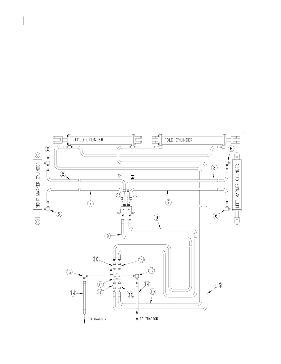
Marker Option
10
5.
Route hoses through marker carrier mount at cut-
out. Then route the hoses along the same path as
opener lift hoses, allowing the same slack at drill
toolbar pivots.
6.
Connect hose from base end of left marker cylinder
to port R1 on sequence valve (2). Connect hose
from base end of right marker cylinder to port R2.
7.
Connect hose from rod end of left marker cylinder
to port C1. Connect hose from rod end of right
marker cylinder to port C2.
8.
Connect 408" hoses (9) to adapters at the front of
the sequence valve. Route hoses along center of
tongue.
9.
Attach adapters (10) to front and rear ports and el-
bows (12) to cross ports of selector valve (11).
10. Assemble hoses (9) to the adapted rear ports of se-
lector valve. Assemble hoses (13) from fold cylinders
to the adapted front ports of selector valve.
11. Assemble hoses (14) to elbows (12) on selector
valve.
12. Lay hoses flat along tool bars. Tie hoses down with
plastic cable ties to prevent pinching or kinking dur-
ing folding.
13. Proceed with "Bleeding Marker Hydraulics", page 11.
Figure 14
Dual Marker Hydraulics with Selector Valve
18880
Refer to Figure 14
3.
Install elbow fittings (6) in cylinder ports.
4.
Assemble 270" hoses (8) to base end elbow fitting
and 277" hose (7) to rod end elbow fitting.