Normal field operations – Great Plains Max Cover Verti-Till Ripper Operator Manual User Manual
Page 29
8/6/07
596-098M
27
Operating Instructions
Normal Field Operations
For drills with S/N: 1025MM and below.
Refer to Figure 18
1.
Lower the frame to a desired tillage depth. The
depth control paddle can be pushed up against
the depth control valve stem and locked with
the knob. The unit will automatically stop at this
depth each time the unit is lowered.
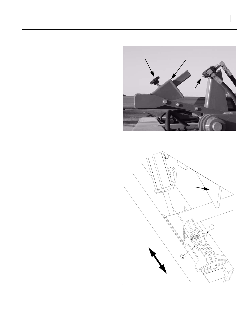
For drills with S/N: 1026MM and above.
Refer to Figure 19
1.
Raise the implement fully and install the cylin-
der locks, see “Lock Cylinders,” page 28. Pull
the spring loaded pin (1) and slide the move-
able depth stop (2) to achieve desired tillage
height and re-engage pin. The top hole allows
for a 16” tilling depth and the lower hole allows
for a 6” tilling depth. Repeat for opposite wheel
arm.
NOTE: Be sure the lock pins are set in the same
holes on both wheel arms.
2.
Adjust the coulters up or down to achieve dif-
ferent tilling, cutting and mixing results. A pilot
operated check valve in the coulter lift circuit
will lock the coulters at the depth you choose.
3.
Always lift the unit out of the ground when turn-
ing at field ends and other short radius turns to
avoid damage and premature wear to the
shanks and coulter gangs.
4.
Both the Auto reset and Rigid shank mounts
are protected by shear bolts for extreme over-
loads. If the shank bolt shears replace the low-
er bolt with the correct shear bolt, use GP part
number 802-060C. (HHCS 5/8-11 x 4 Gr5)
Note: For your convenience a series of holes in 4
gussets on the rear of the machine have been pro-
vided for spare shear bolt storage.
Figure 18
Depth Control Paddle
21660
Knob
Paddle
Valve Stem
Deep
16”
Shallo
w
6”
Frame
Bumper
Figure 19
Manual Depth Stop
22563