Rolling harrow assembly – Great Plains VT7300 Operator Manual User Manual
Page 7
6/30/2008
Verti-Till VT5300-VT9225 Finishing Attachments 596-156M
5
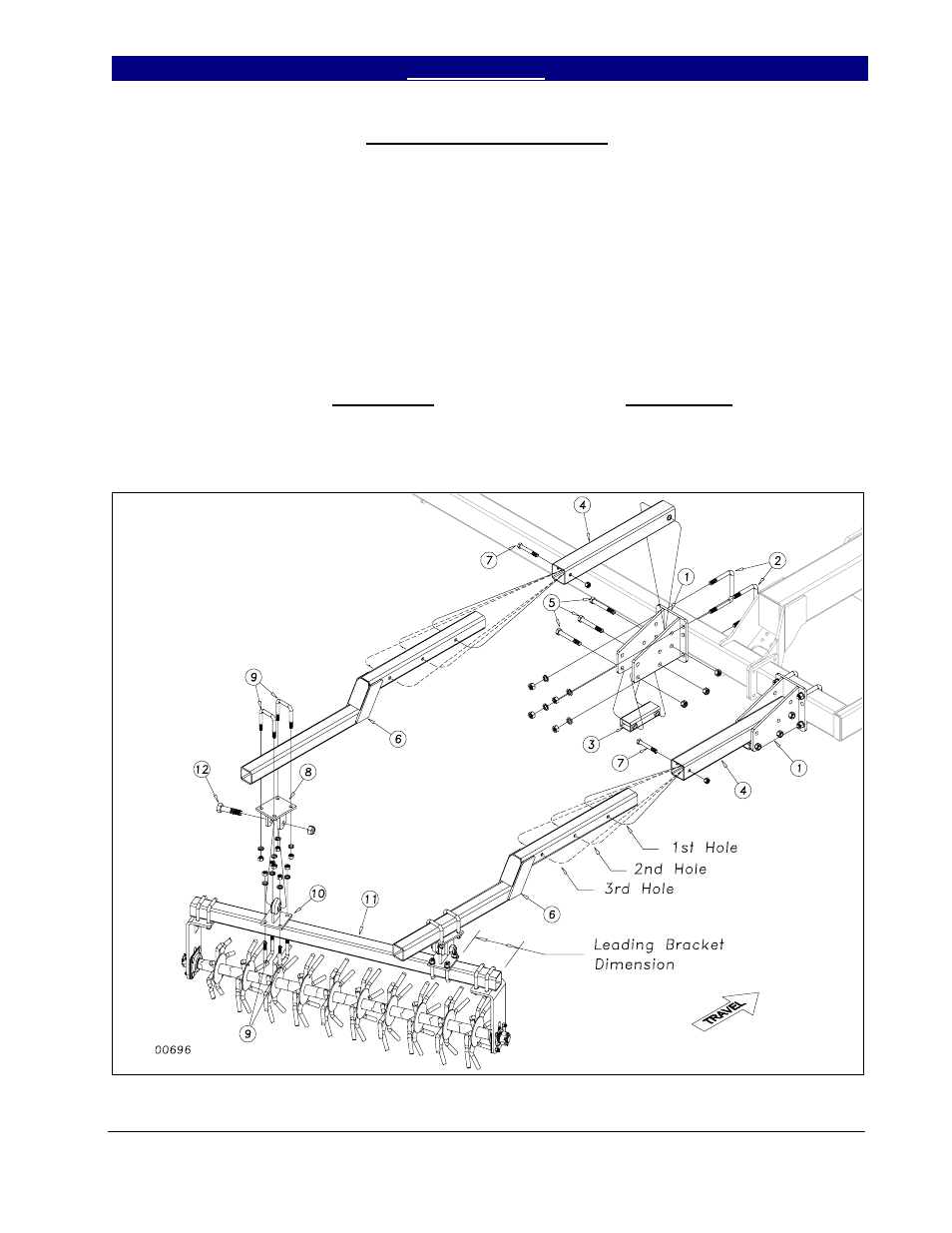
Rolling Harrow Assembly
Move the machine to a safe, clean
working area before proceeding. Start by U-
bolting the VT rolling harrow brackets (1) to
the rear bar of the Verti-till as shown in Figure
2. Use 3/4 x 6 x 5 5/8 u-bolts (2) with lock
washers and hex nuts. Refer to Section 6
Machine Layouts for placement dimensions.
Bolt the VT rolling harrow arm rest (3) and
rolling harrow sleeve (4) to the harrow bracket
(1) with three 3/4 x 5 1/2 hex bolts (5) using
lock nuts. Draw up snug but do not torque,
arm must move freely. Slide the VT rolling
harrow arms (6) into the harrow sleeves (4) and
bolt through the proper hole with 5/8 x 4 1/2
hex bolts (7) using 5/8 lock nuts.
U-bolt the rolling harrow brackets (8) to
the harrow arms (6) using 5/8 x 3 x 4 1/2 u-
bolts (9) and lock washers and hex nuts. U-bolt
the ball-joint brackets (10) to the rolling harrow
module (11) with same hardware as above
placing the leading bracket at the dimension on
the layout. Tighten the leading ball joint
bracket down and leave the rear bracket loose.
Attach the harrow module (11) to the harrow
arms (6) with the 1 x 4 hex bolts (12) using a
nylon lock nut. Do not torque nylon lock nut.
After verifying the placement dimensions on
the layout drawing, finish tightening the
remaining u-bolts on the brackets.
Figure 2