Install ground drive assembly, Re-install pump, Or step 28 – Great Plains Ground Drive Fertilizer Pump Yield Pro Planters User Manual
Page 6: Ior to step 28. if left r
Great Plains Mfg., Inc.
6
Ground Drive Fertilizer Pump
407-149M
04/23/2007
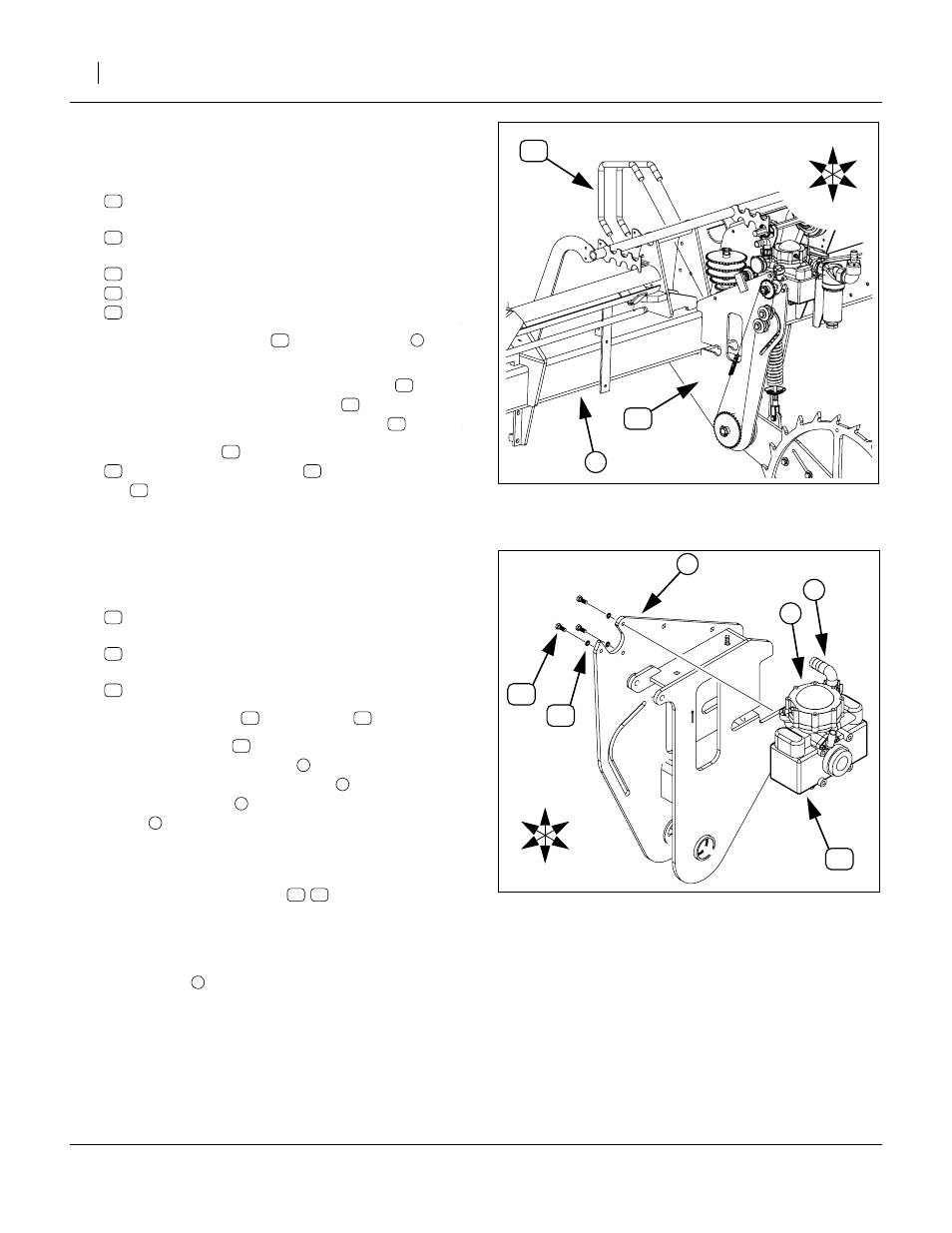
Install Ground Drive Assembly
Refer to Figure 7, which depicts the new ground drive with guards
removed. Guards may be left in place until final sprocket mounting.
26. Select one new:
407-147K FERTILIZER PUMP DRIVE ASY KIT
two new:
806-102C U-BOLT 3/4-10 CORNER 7 SQ
four sets new (not shown):
804-025C WASHER FLAT 3/4 SAE PLT
804-023C WASHER LOCK SPRING 3/4 PLT
803-027C NUT HEX 3/4-10 PLT
27. Position the two U-bolts
over the tool bar
the mount location.
28. Have assistant(s) hold the drive assembly
the mount point. Insert the U-bolts
. Temporarily
hold the assembly in place with four nuts
29. Remove one nut
at a time. Place a flat washer
(not shown), lock washer
(not shown) and
nut
on the U-bolt. Tighten each until the drive
assembly’s mount is flat against the tool bar.
Tighten to torque spec.
Re-Install Pump
30. Select the saved
three new
802-314C HHCS M8X1.25X20 GR8.8
and three new
804-157C WASHER SPRING LOCK M8 PLT
31. Place lock washers
32. Position the pump
at the top cut-out of the con-
tact wheel mount weldment
against the inside of the left plate
upper air chamber
of the pump is Up, the inlet
elbow
is in Front, and the threaded holes on the
three-hole side of the pump match the three holes
in the plate
Insert three bolts/washers
33. Re-connect hose from strainer to pump inlet (not
shown) and secure with saved clamp.
34. Re-connect manifold hose (not shown) to pump
outlet elbow
and secure with saved clamp.
U
D
L
R
B
F
Figure 7
Install Ground Drive
25307
1
1
U
D
B
F
R
L
Figure 8
Re-Install Pump
25308
1
2
3
1
1