Hydraulic gauge wheel assembly – Great Plains 7552 Series VII Operator Manual User Manual
Page 30
Series VII 6326-7552 Discovator 550-221M
3/31/2004
26
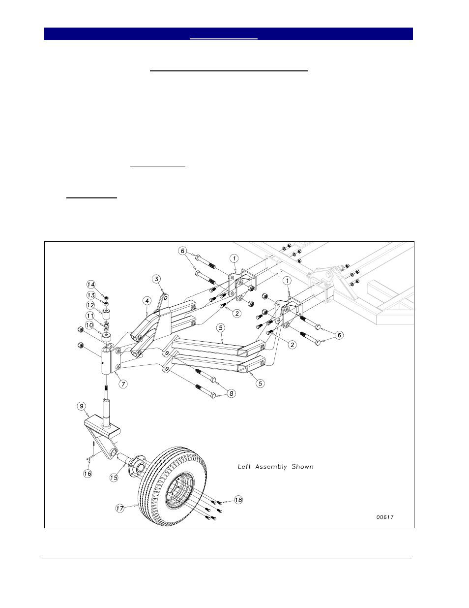
Hydraulic Gauge Wheel Assembly
On model 6542, 7548 & 7552, bolt the
gauge wheel arm mount clevis (1) to the front
bar of wing brace as shown in Figure 14 using
the 5/8 x 1½ hex bolts (2), lock washers and
hex nuts. Insert the linkage arms (3) and (4)
and hydraulic gauge wheel arms (5) into the
arm clevis (1). Assemble with 1 x 6 hex bolt
(6) and nylon lock nut. Do not torque down.
Bolt the pivot bracket (7) to the arms as shown
with 1 x 7 hex bolt (8) and nylon lock nut,
again do not torque. Insert the appropriate left
or right gauge wheel arm (9) into the pivot
bracket (7) and install the friction cap (10),
spring (11), spring cover (12), ¾” hex nut (13)
and ¾” jam nut (14) to secure the assembly.
Insert the hub and spindle assembly (15) into
the gauge wheel arm (9), using anti-seize
material on the spindle. Secure with 5/16 x 3
clevis pin (16) and 1/8 x 1 cotter. Bolt on the
rim and tire assembly (17) with six ½ x 1¼
lug bolts (18). Install the gauge wheel
hydraulic cylinders (or ratchet jacks) as per
hydraulic layout for your machine, section 2.
Use 1 x 8½ eye-bolts with 1” jam nuts at the
base of the cylinders. For directions on the
proper setting for the hydraulic gauge wheel
during operation, refer to section 5.
Figure 14
11/22/2004