Great Plains 7552 Series VII Operator Manual User Manual
Page 104
Section 5: Operating and Maintenance
Series VII 6326-7552 Discovator 550-221M
1/19/2006
100
General Operation Instructions and In-Field Adjustments
1. Remove the transport pins and unfold the
machine. Make sure the fold cylinders are fully
extended to allow the wings to fully flex in the
field.
2. If possible have someone observe the machine
during first time operation for levelness—front
to rear and wings to center frame. Adjust each
as needed. For front to rear, either extend or
shorten the length of the turnbuckle on the self-
leveling. Never run the machine with the back
lower (deeper) than the front. To adjust the
machine from side to side, use the eyebolt on
each wing. Adjust the inside wings first and
then the outside wings. The gauge wheels
should be set in field position to be ½” to 1 ½”
off the ground.
3. The ideal working speed for the Discovator is
5 ½ to 6 ½ mph. Working too slow may cause
plugging, poor incorporation or mixing of crop
residue and reduced weed kill. Running too
fast may cause streaks in chemical
incorporation and ridging.
4. The Discovator is designed as a secondary
tillage tool and is designed to leave a finished
seedbed following some form of fall or spring
tillage. For best results, if at all possible, run
the machine at a slight angle to the rows. This
will improve trash flow and help spread the
residue more evenly throughout the field.
5. When you have the machine set to the desired
working depth, set the depth stop slide on the
depth control bar. This is located at the front of
the machine on the brace bar. This will
maintain a constant depth each time after
raising and lowering the machine.
6. If after setting the depth stop, the detent on the
tractor kicks out before the stop contacts the
button on the depth stop, slow the hydraulic
flow speed down. If this problem still persists,
contact the factory service representative for
other possible adjustments. Do not try to
adjust the rebound valve without first
contacting the factory service rep.
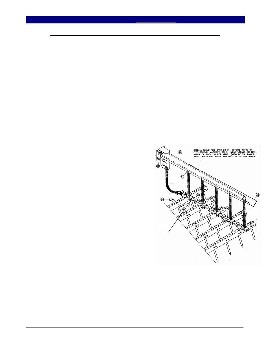
7. Adjust the drag to leave the desired results
while maintaining the trash flow through the
drag.
a.) On the spike drag, start with 5 links
hanging from the chain in drag arm bottom
slot. (This is the starting point for worst
conditions.) The cleaner the ground, the
shorter the pull chain may be pulled up.
On the spike drag, one of the links in the
first row of angles is turned over. This
allows the trash to start flowing through the
drag easier by changing the angle of the
first row of teeth. Always make sure that
the drag is never pulling off the hang
chains. If so, shorten pull chains.
b.) On coil tine drags, start with the top
eyebolt (12) centered. Then level drag
mainframe (4R and 4L) by changing
position of leveling bolt (21). There are
two holes in the arm and four in the
mainframe. One of these will get you
where you need to be to level. To lay the
teeth back, remove the clip pin (42) on
each end and move strap adjustment by
pushing the handle (7) forward. This strap
has 5 holes and will let you lay the teeth
back several degrees. If it is desired to set
one row, usually the first, different than the
rest as far as the angle is concerned, it can
be adjusted individually by loosening the
U-bolt and set- screw on each end of the
ASSEMBLE WITH LINK UP AS
SHOWN. IN SOME
CONDITIONS THE FRONT
LINK MAY BE ASSEMBLED
DOWN TO HELP START
TRASH TO FLOW THROUGH
THE HARROW.