Hitch tongue, side plate and level bar assembly – Great Plains 7552 Series VII Operator Manual User Manual
Page 25
3/31/2004
Series VII 6326-7552 Discovator 550-221M
21
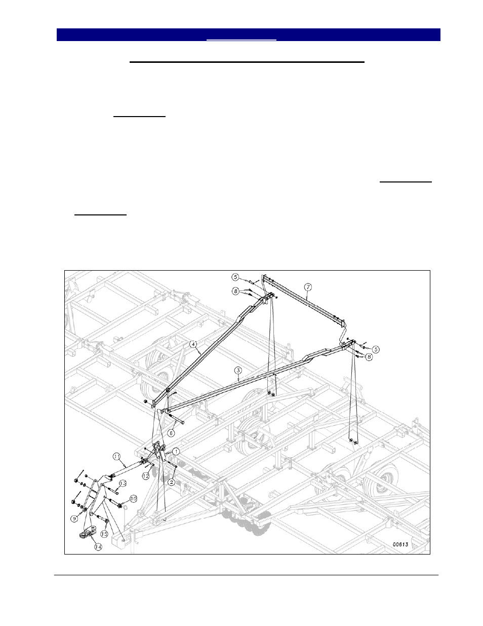
Hitch Tongue, Side Plate and Level Bar Assembly
Slide the H-bracket (1) down over the
hitch pole as shown in Figure 8. Bolt in place
with a ¾ x 8 bolt (2) and ¾” lock nut. Draw
this nut up but do not torque, as this part must
pivot.
Insert the level bars (3) and (4) through
the previously assembled truss and connect to
the torque tube using two 1 x 3 3/8 usable
clevis pins (5), 1” flat washers, one 1” machine
washer and 3/16 x 2 cotter pins. Install the 1 ¼
x 13½ GR 8 bolt (6) through the level bars and
H-bracket. Draw up snug with a 1¼ top lock
nut (do not torque).
Connect the level bar cross brace (7)
between the level bars and bolt in place with ¾
x 2 hex bolts (8) using hex nuts and lock
washers. Slide the side plate weldment (9) over
the end of the hitch and bolt in place as shown
with the 1½ x 12 safety chain hitch bolt (10).
Secure with 1½ slotted hex nut and ¼ x 3 cotter
pin. Use the 1½ machine washers as needed
for proper fit. Connect the turnbuckle (11)
between the side plate assembly and the H-
bracket (1). Use a 1 x 3 3/8 usable clevis pin
(12) with machine washer and 3/16 x 2 cotter
pin at the back end of turnbuckle. Use a 1 x 9
GR 8 bolt (13) with a nylon lock nut at the tee
end of the turnbuckle. Snug, but do not torque
nylon lock nut.
Insert the hitch clevis (14) into the front
of the side plate weldment (9) and bolt in place
with a 1½ x 9 3/8 hitch bolt (15). Secure with
slotted hex nut, machine washers and ¼ x 3
cotter pin, using the 1½ machine washers again
as needed for proper fit.
Figure 8
11/22/2004