Center wing stop and outside wing stop assembly – Great Plains 7552 Series VII Operator Manual User Manual
Page 28
Series VII 6326-7552 Discovator 550-221M
3/31/2004
24
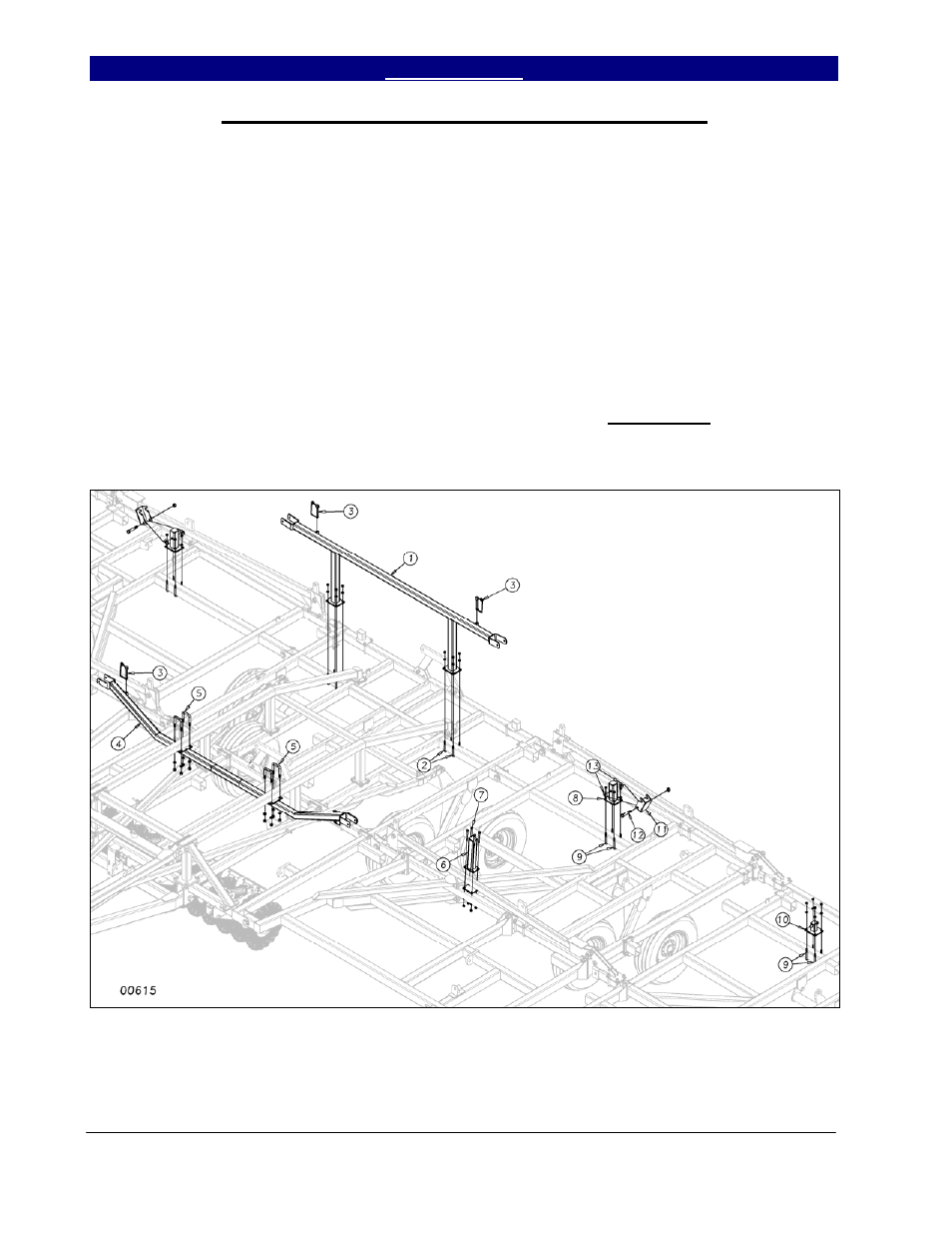
Center Wing Stop and Outside Wing Stop Assembly
U-bolt the center wing stop (1) to the
second bar from the rear on the center frame as
shown in Figure 12. Use 1/2 x 3 x 5 u-bolts
(2) with lock washers and hex nuts. Center the
wing stop from side to side. Insert the ½ x 4½
transport lock quick pins (3) in the holders on
the wing stop.
On models 7548 & 7552, u-bolt the
front center wing stop (4) to the bottom of the
center frame truss using 5/8 x 3 x 4½ u-bolts
(5), lock washers and hex nuts. Bolt the wing
rest (6) to the rocker/fold bracket with 4-hole
clamp plate and ½ x 4½ hex bolts (7), lock
washers and hex nuts (See layout for
placement).
On 5-section models, u-bolt the wing
lock mount (8) on the inside wing with ½ x 3 x
5 u-bolts (9). U-bolt the wing lock “T”
bracket (10) on the outside wing with the same
½ x 3 x 5 u-bolt (9). Refer to the shank layout
for your particular model for the exact location
of the wing lock mount and lock “T” bracket.
Use lock washers and hex nuts on these u-
bolts. Bolt the wing latch (11) to the wing lock
mount (8) with a ¾ x 4½ bolt (12). Slide a ¾
flat washer (13) between the latch and the
mount on each side to take out the slop. Use a
¾” lock nut but do not torque down. The
latch must move freely.
Figure 12