Great Plains 2SNT30 Assembly Instructions User Manual
Page 9
4/8/04
1-8
MARKER HYDRAULIC SYSTEM INSTALLATION
INSTALLING: 24 or 30' SINGLE MARKER HYDRAULICS
GENERAL NOTE: JIC fittings do not require high torque. JIC and O-ring fittings do not require sealant. To avoid crack-
ing fittings or castings from overtightening, DO NOT use plastic sealant tape.
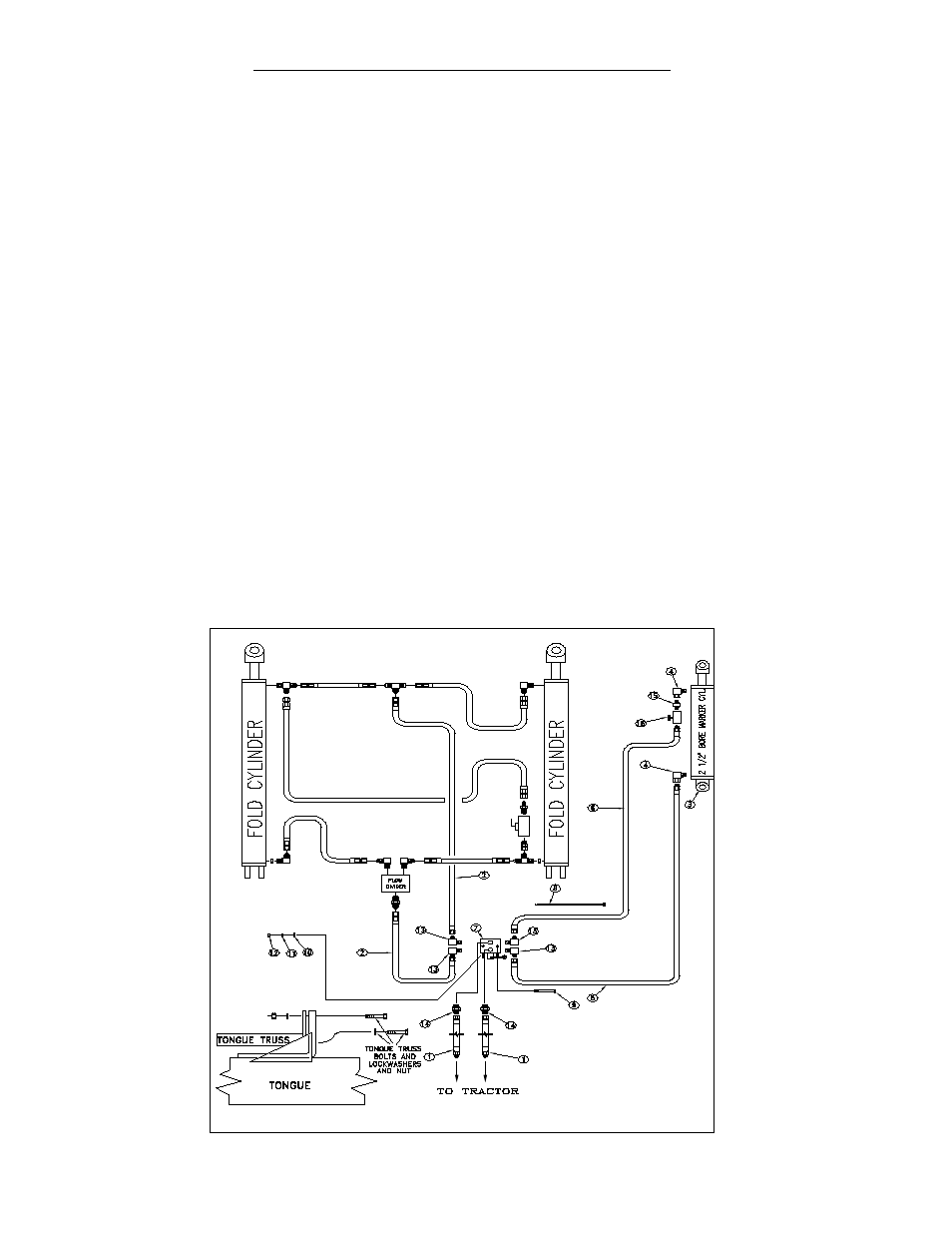
REFER TO THE PICTORIAL HYDRAULIC SCHEMATIC Fig. 7 WHEN INSTALLING SINGLE MARKER HYDRAU-
LICS.
1. Attach the 90˚ swivel elbow (#4) to the base and rod end of the marker cylinder (#3). Thread the close nipple (#15)
in the swivel of the elbow (#4), and thread the needle valve (#16) on the close nipple.
2. Uncoil and attach hose (#6) to the needle valve (#16) on the rod end of the marker cylinder (#3). Uncoil and attach
hose (#5) to the swivel elbow (#4) attached to the base end of the marker cylinder (#3). Route these two hoses through
the frame member cut-outs and hose clamps. Parallel to the hoses feeding the outer gage wheel cylinder as shown in
Fig. 8 on page
1-9. Place the hoses in the clamps later, after the free ends are plumbed.
3. Referring back to schematic Fig. 7, Bolt the selector valve (#7) to the tab provided on the carrier lug cross member.
(The carrier cross member can be identified as part #5, page 1-1 in the Main Frame Parts Drawing in the Parts section
of your 2SNT Drill Owners Manual). The valve is held in place with bolts (#9), flat washers (#10), lock washers (#11)
and nuts (#12).
4. Install the four elbow fittings (#13) in the side ports of the selector valve (#7). Install the two straight fittings (#14) in
the two top ports of the selector valve (#7).
5. Locate the two long hoses (#1) coming from the tractor, going to the fold cylinders. Break the first hose at the "T"
between the rod end of the fold cylinders, the second at the flow divider. Take these same two hoses and install them
on the top two selector valve fittings (#14).
6. The two hoses just removed from the fold cylinders are replaced by two shorter hoses (#2). Run one from the "T"
between the rod end of the fold cylinders to the elbow (#13) on the side of the selector valve. Run the other from the
fold cylinder's base end flow divider to the adjacent elbow (#13).
7. The last hoses to connect should be the two coming from the marker cylinder. Connect these to the two remaining
elbows (#13) on the selector valve (#7) as shown.
Single Marker Hydraulics
Fig. 7
11165
To Tractor