Great Plains 2SNT30 Assembly Instructions User Manual
Page 7
4/8/04
1-6
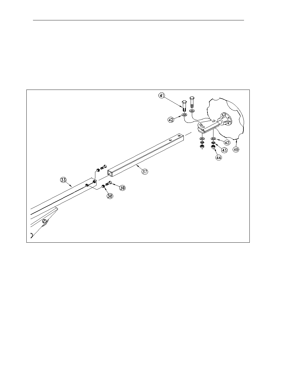
7. Referring to Fig. 5, slide the fourth section tube (# 37) inside the 3rd section (# 33). The holes in the 4th section must
be to the outside of the drill and need to be on the top and bottom side as shown. Thread the jam nuts (# 38) on the
square headed set screws (# 39). Thread the set screws into the nuts welded to the outer end of the 3rd section (# 33).
Tighten the set screws and jam nuts.
8. Again referring to Fig. 5, slide the blade and spindle assembly (# 40) over the 4th section tube (# 37).Pass the bolt
(# 41) through a flat washer (# 42), through the hole in the spindle weldment, and through the holes in the 4th section
tubing. Complete the joint by fastening a flat washer (# 42), a lock washer (# 43) and a nut (# 44) onto the bolt. In a
similar manner, install the second bolt through the adjustment slot, next the first bolt. Tighten these two nuts.
11103
Fig. 5
INSTALLATION INSTRUCTIONS: 1992 2SNT 24’ & 2SNT 30’ MARKERS (CON’T.)