Great Plains CP1000 Assembly Instructions User Manual
Page 9
7
Section 1 Assembly Instructions & Set-Up
9/21/05
CPH and CP1000 Coulter Command System 148-258M-B
Great Plains Mfg., Inc.
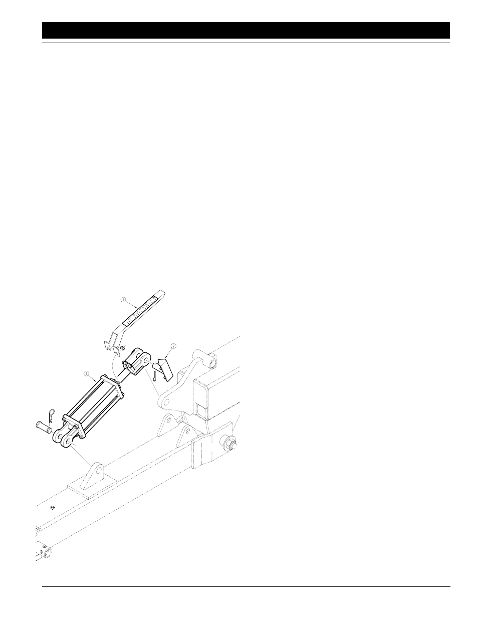
Tongue Cylinder
Refer to Figure 4
1.
Remove the stroke pointer gauge (#1) which was
bolted to the rod end of the tongue cylinder and re-
torque the cylinder tie rod bolts to 95 FT-LBS. Re-
move the stroke pointer (#2) at the cylinder rod
clevis and discard it.
Refer to Figure 5
2.
Turn the tongue cylinder with the rod end pointing
forward and down, and with the ports turned up. Use
the clevis pin (#17), flat washer (#18), and 1/4" cot-
ter pin (#13) to replace the stroke pointer pin at what
is now the base end of the cylinder. Use the existing
clevis pin (#15) and hair pin cotter (#16) to connect
the rod end to the tongue.
3.
Remove the elbow fitting (#3) at the base end of the
tongue cylinder and screw the 1/16" orifice plate
(#9) into the base end port. Screw the orifice plate in
far enough so it doesn't interfere with the elbow fit-
ting and replace the fitting.
IMPORTANT: Failure to install the orifice plate will not al-
low coulter command to operate correctly.
Hydraulic Control Valve
Refer to Figure 5
1.
Bolt the 3 1/2" x 3 1/2" x 5" hydraulic valve block (#2)
to the top of the valve mount bracket (#13) with the
5/16" x 4" long bolts (#1), lock washers (#11), and
hex nuts (#10). Position the valve block so the sole-
noids set above the middle of the top surface of the
valve mount.
2.
Bolt the 3" x 3 1/4" x 8" hydraulic valve block (#25) to
the side of the valve mount bracket (#13) with the
5/16" x 3 1/2" long bolts (#24), lock washers (#11),
and hex nuts (#10). Position the valve block so the
four ports point away from the valve mount and the
solenoid points up.
3.
Bolt the valve mount assembly to the hitch with the
1/2" x 5 1/2" long bolt (#12), lock washer (#6), and
hex nut (#5). Assemble the bolt through the pivot
tube for the level link located just behind the tongue
cylinder. Position the valve mount so the dual sole-
noids face toward the rear of the machine.
4.
Assemble the 3/4" JIC elbows (#3) to the valve ports
marked "P" and "T" of the top valve block. Assemble
the straight 3/4" adaptors (#7) to the valve ports
marked "A" and "B" of the top valve block. Assemble
the straight 3/4" adaptors (#7) to the valve ports
marked "V1" and V2" of the lower valve block. As-
semble the 1/2" female pipe swivel elbows (#20) to
the valve ports marked "C3" and "C4" of the lower
valve block. Assemble the 9/16" elbows (#21) to the
valve ports marked "C1" and "C2" of the lower block.
Assemble the remaining two 9/16" elbows (#21) to
the ports on the side of the 1 1/2" x 4" gauge wheel
lift cylinder (#23).
5.
Remove the 122" hoses (#4) from the tongue cylin-
der and assemble them to the elbows (#3) at ports
"P" and "T" on the top hydraulic valve. Connect the
20" long hose (#8) between the port "B" of the top
valve and the tongue cylinder base end fitting. Con-
nect the 30" long hose (#14) between port "A" of the
top valve and the tongue cylinder rod end fitting. As-
semble the other two 122" hoses (#4), from the
Coulter Command kit, to the adaptors (#7) at ports
"V1" and "V2" on the lower hydraulic valve. Remove
the quick couplers from the ends of the long trans-
port lift hoses (#26) and assemble them to the ends
of the 122" hoses (#4) from ports "V1" and "V2". As-
semble the long transport lift hoses (#26) to the el-
bows (#20) at ports "C3" and "C4" on the lower
hydraulic valve. The hose coming from the base end
of the transport lift cylinders connects to the port
marked "C3" and the hose coming form the rod end
of the transport lift cylinders connects to the port
marked "C4". Slide the excess hose from the long
transport lift hoses into the 8" x 8" hitch main tube.
Connect one of the 36" long 1/4" hoses (#22) be-
tween the port "C1" of the lower valve block and the
Figure 4
Tongue Cylinder Disassembly
12672