Coulter command assembly adjustments – Great Plains CP1000 Assembly Instructions User Manual
Page 11
9
Section 1 Assembly Instructions & Set-Up
9/21/05
CPH and CP1000 Coulter Command System 148-258M-B
Great Plains Mfg., Inc.
Control Box
Refer to Figure 6
1.
Mount the control box at a convenient location in the
tractor cab. Connect the 12’ extension cable to the
9-pin connector on the back of the control box and
route the cable back toward the tractor drawbar area
making sure it will not get kinked or pinched.
2.
Connect the power cord to a good uninterrupted 12
volt power source on the tractor. Connecting directly
to the battery is recommended. Plug the cord into
the lead with the 2-Pin connector on the back of the
control box. The polarity of the power supply is very
important to prevent circuit damage. The white wire
of the power cord must be connected to the "+" pos-
itive battery terminal and the black wire to the "-"
negative battery terminal.
Coulter Command
Assembly Adjustments
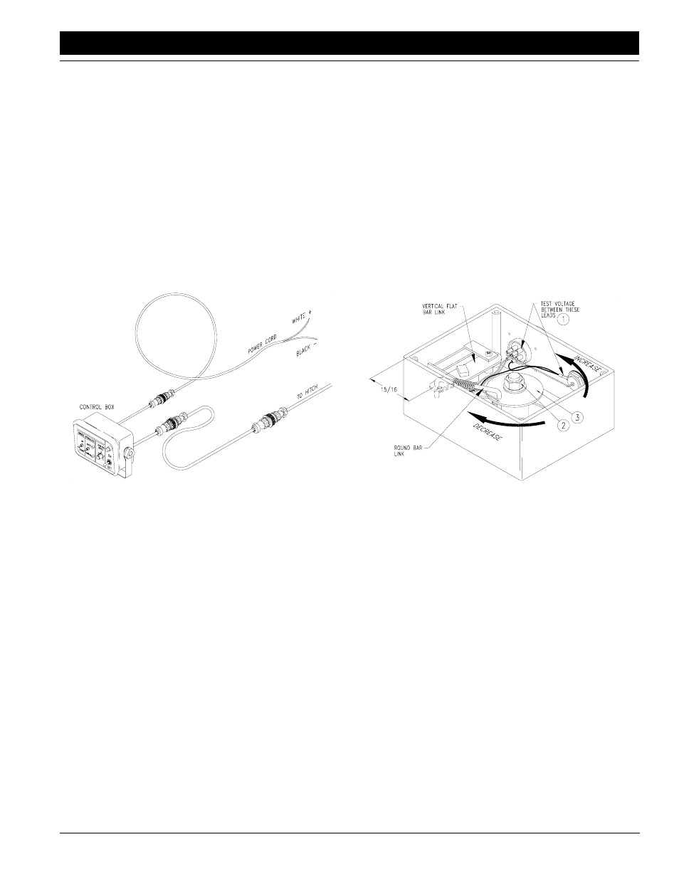
Refer to Figure 7
Coulter command depth sensing wheel assemblies
which are pre-assembled at the factory are pre-adjusted
and should not require further adjustment. If the sensor
box at the depth sensing wheel has been field installed,
or if its linkage gets out of adjustment, it must be adjust-
ed using one of the following two procedures:
1.
The best and most accurate means of adjusting the
linkage inside the sensor box makes use of a volt-
meter which reads 0-12 volts DC. The Control Box in
the tractor must be properly connected to a power
source and the POWER switch must be ON. The
TONGUE HYDRAULICS switch should be in the
MANUAL mode. The wiring harness must be con-
nected to the control box and the sensor box. The
depth sensing wheel should be off the ground with
the arm rotated down as far as its spring-loaded
down-pressure link will allow. Remove the cover
from the sensor box and inspect the internal linkage
for proper assembly.
Figure 6
Coulter Command Control Box
12575
With the depth sensing wheel in the max down posi-
tion, the voltage potential between the lead contain-
ing the WHITE WIRE and the ground lead (BLACK
WIRE) in the gauge wheel sensor box (#1) should
be 5 volts DC plus or minus 1/4 volt. To adjust the
gauge wheel sensor box linkage, loosen the 3/8"
hex flange nut (#2) on the sensor spindle and rotate
the circular disk (#3) until the voltage potential be-
tween the lead containing the WHITE WIRE and the
ground lead (BLACK WIRE) (#1) is 5 volts DC plus
or minus 1/4 volt. Rotating the circular disk counter-
clockwise increases voltage potential, and rotating
the circular disk clockwise decreases the voltage
potential. Once the correct voltage potential is
achieved, tighten the 3/8" nut. Be careful not to ro-
tate the circular disk as you tighten the nut. Replace
the sensor box cover.
2.
The second means of adjusting the linkage inside
the sensor box involves measuring from the inside
edge of the box to the left pivot of the formed round-
bar link. The depth sensing wheel should be off the
ground and rotated down as far as its spring-loaded
down-pressure link will allow. Remove the cover
from the sensor box and inspect the internal linkage
for proper assembly.
With the depth sensing wheel in the max down posi-
tion, the pivot between the vertical flat-bar link and
the formed round-bar link should be 15/16" from the
front inside edge of the sensor box.
With the sensor box linkage properly assembled,
loosen the 3/8" hex flange nut on the sensor spindle
and rotate the circular disk until the pivot between the
vertical flat-bar link and the formed round-bar link is
15/16" + or - 1/16" from the front inside edge of the
box. Be careful not to rotate the circular disk as you
retighten the nut. Replace the sensor box cover.
3.
Some models of the sensor box have a mark on the
vertical flat-bar link which should line up with a mark
on the link’s slotted mount plate at the correct preset
voltage. With the depth sensing wheel in the max
down position, the marks should line up at a voltage
of 5 volts DC + or - 1/4 volt. Aligning the marks is more
Figure 7
Sensor Box Adjustments
12619