Great Plains CP1000 Assembly Instructions User Manual
Page 8
6
Section 1 Assembly Instructions & Set-Up
CPH and CP1000 Coulter Command System 148-258M-B
9/21/05
Great Plains Mfg., Inc.
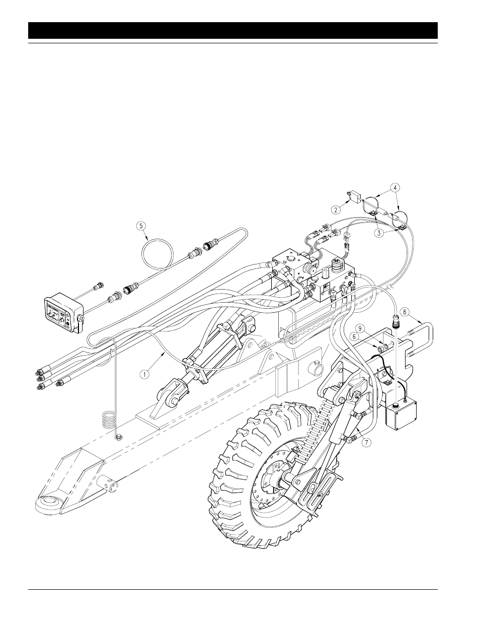
Refer to Figure 3
1.
Route the 156" long two wire lead of the wiring har-
ness (#1) through the 8" x 8" hitch tube and to the lift
switch (#2) at the rear of the machine. Plug in the lift
switch and support the cable with the cable tie
mounts (#3) and releasable cable ties (#4) or strap
the cable to the hydraulic hoses.
2.
Plug the 4-Pin connector of the wiring harness to the
sensor box on the depth sensing wheel and support
the cable with the cable tie mounts (#3) and releas-
able cable ties (#4).
3.
Route the 9-Pin connector through the spring hose
loop and to the tractor hitch. This will plug into the 9-
Pin Female lead from the control box extension ca-
ble (#5).
4.
The other three short leads on the wiring harness
will plug into the leads from the solenoids on the hy-
draulic control valves after they are installed.
Figure 3
Wiring Harness Assembly
12617