Great Plains 24F Assembly Instructions User Manual
Page 4
118-073M
4/5/2006
Great Plains Mfg., Inc.
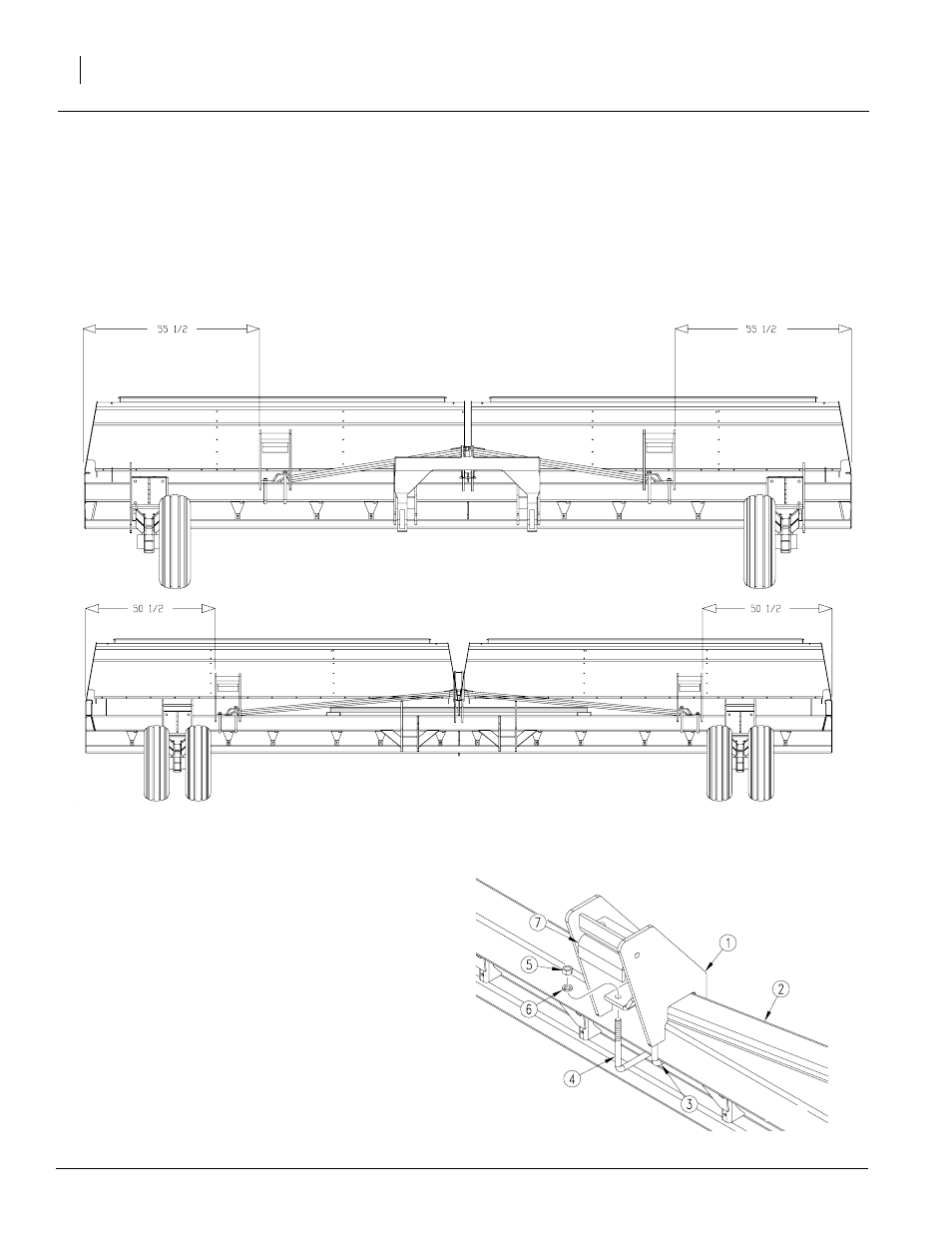
Weight Bracket Kit
4
20F Weight Bracket Layout
24440
Refer to Figure 2
4.
Determine which weight bracket is LH
bracket and which is RH bracket. NOTE:
There is a cut-out notch on one side of
each bracket. The notched side goes
toward center of drill to allow clearance
for frame brace.
5.
Place LH bracket on LH-side drill frame.
Place RH bracket on RH-side drill frame.
Refer to Figure 3
6.
Secure weight bracket (1) to frame (2) us-
ing u-bolts (3 and 4), 3/4 lock washers (6),
and 3/4-10 hex nuts (5).
NOTE: Use longer u-bolt (3) to secure
frame (2) to raised portion of bottom of
weight bracket (1).
7.
Position adjustment leg (7) against weight
edge for additional support. Tighten bolts
securing adjustment leg to bracket.
8.
Complete steps 5 through 8 for both
weight brackets.
24444
Figure 3
Secure Weight Bracket to Frame
Figure 2
Weight Bracket Placement
24F Weight Bracket Layout
24449