Great Plains 24F Assembly Instructions User Manual
Page 2
118-073M
4/5/2006
Great Plains Mfg., Inc.
Weight Bracket Kit
2
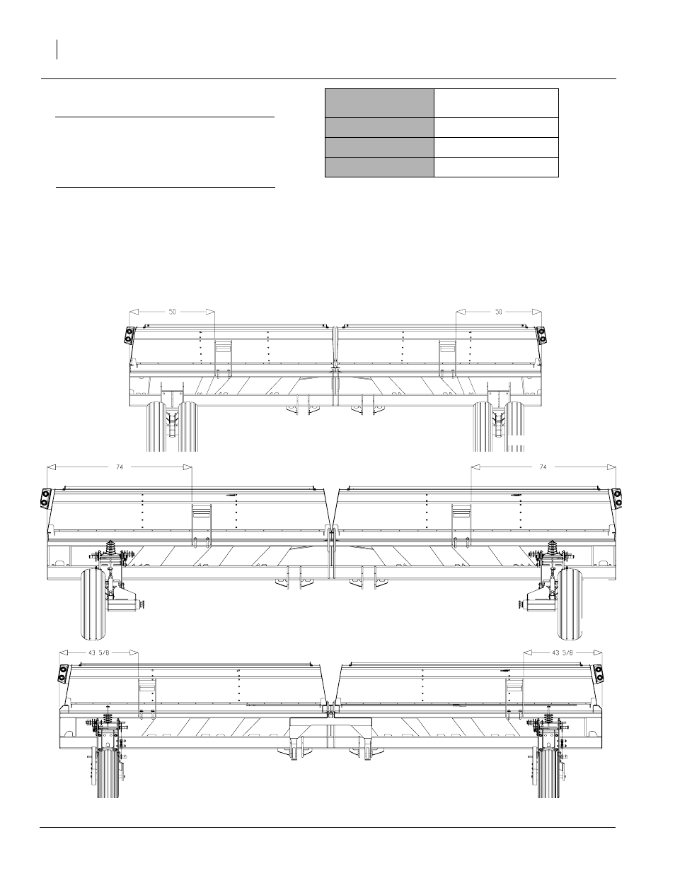
Refer to Table 1
IMPORTANT! The chart to the right gives the rec-
ommended placement for LH and RH weight brack-
ets. However, weight brackets may be placed
anywhere along frame provided there are no clear-
ance issues.
4.
For both LH and RH brackets, measure the dis-
tance given in the chart for the appropriate drill
model. NOTE: Measure distance from each end
of drill frame towards center of drill.
Refer to Figure 2
5.
Place weight bracket on drill frame.
Drill Model
Distance From End of Drill
Frame
20P
50 inches
24P
74 inches
25P
43 5/8 inches
Table 1
25P Weight Bracket Layout
24439
Figure 2
Weight Bracket Placement
24P Weight Bracket Layout
24447
20P Weight Bracket Layout
24448
This manual is related to the following products: