Great Plains 24F Assembly Instructions User Manual
Page 3
4/5/2006
118-073M
Great Plains Mfg., Inc.
3
Installation Instructions
Refer to Figure 3
6.
Secure weight bracket (1) to frame (3) using
two 3/4-10 x 5 1/32 x 4 u-bolts (2), 3/4 lock
washers (5), and 3/4-10 hex nuts (4).
7.
Position adjustment leg (6) against weight edge
for additional support. Tighten bolts securing
adjustment leg to weight bracket.
8.
Complete steps 5 through 8 for both weight
brackets.
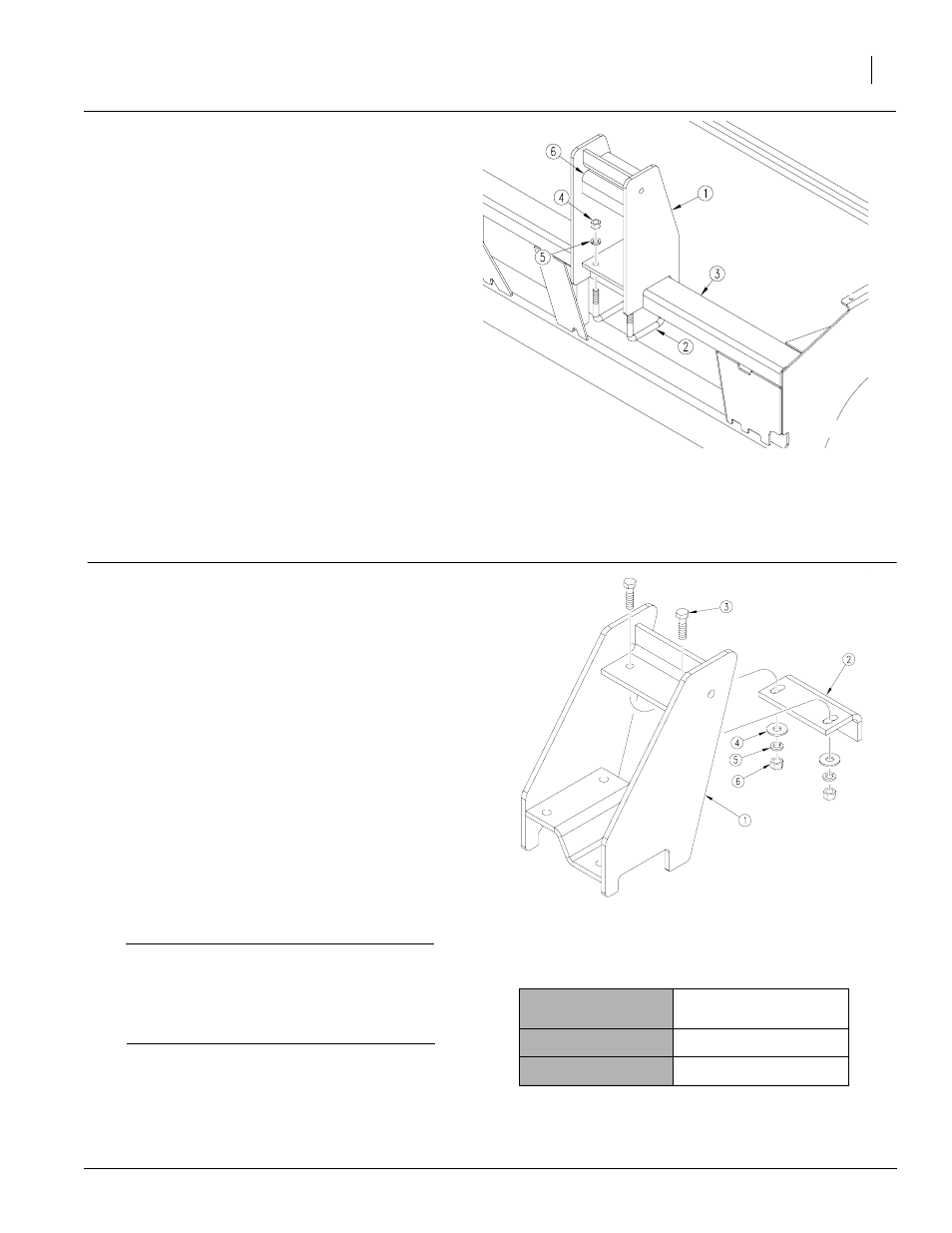
Assembly Instructions for 118-072A
24445
NOTE: The 20F and 24F Weight Bracket Kit
comes with specific LH and RH weight brack-
ets.
Refer to Figure 1
1.
Attach weight bracket adjustment leg (2) to
both LH and RH weight bracket weldments (1).
2.
Secure adjustment leg (2) to weldment (1) us-
ing two 5/8-11 x 2 1/4 bolts (3), 5/8 flat washers
(4), 5/8 lock washers (5), and 5/8-11 hex nuts
(6). Leave bolts loosened for adjustment.
Refer to Table 1
IMPORTANT! The chart to the right gives the
recommended placement for LH and RH weight
brackets. However, weight brackets may be
placed anywhere along frame provided there
are no clearance issues.
3.
For both LH and RH weight brackets, measure
the distance given in the chart for the appropri-
ate drill model. NOTE: Measure distance
from each end of drill frame towards center
of drill.
Drill Model
Distance From End of Drill
Frame
20F
55 1/2 inches
24F
50 1/2 inches
Figure 1
Weight Bracket and Adjustment Leg
Table 1
24446
Figure 3
Secure Weight Bracket to Frame