Great Plains 2SNT30 Assembly Instructions User Manual
Page 6
4/9/04
1-4
113-395M
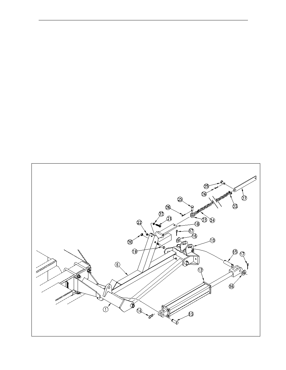
4. Referring to Fig. 2, pin the base end of the hydraulic cylinder (# 12) to the marker mount (# 1) using the pin and re-
tainer (#13 & 14). Remove the plastic shipping plugs from the cylinder ports, and pull the rod end of the cylinder out to
its maximum length. Pin the rod end of the cylinder by working the cylinder pin (# 15) through one slotted ear on the
breakaway hinge (# 10), through the cylinder's rod end clevis, and out the other ear on the hinge. The rod end pin is
retained by placing the flat washers (# 16) on the outside of the slotted ears, and cotter pins (# 17) through the holes in
the pin.
Again referring to Fig. 2, install the chain bar weldment (# 18) on the first section (# 6). The chain bar should pivot freely
around the bolt (#19) which is fastened with lock nut (# 20). Directly below the pivot bolt for the chain bar weldment (#
18) is a single hole in which the full threaded adjustment bolt (# 21) is installed. To install, first thread one lock nut (# 22)
up the entire threaded length of the bolt. Next, push the bolt with nut through the hole in the mast of the first section (#
6), and complete the assembly by threading a second lock nut (# 22) up the entire remaining length of the full threaded
bolt.
Information on the adjustment of this bolt, which is designed to take the slack out of the chain when the marker is in the
folded position, can be found in the "Adjustments" section on page
12. For now, it is important that the head of the
adjustment bolt extend as little as possible which will prevent the parts from being damaged the first time the marker is
folded.
Thread a utility clevis (# 23) through one end of the chain (# 24). Pin this clevis to the chain bar weldment (# 18) using
the pin and cotter (# 25 & 26) that came with the utility clevis. Do not fully bend the cotter pin at this time, the chain will
be adjusted later before the marker is folded for the first time. Chain length adjustments are done at the end of the chain
towards the center of the drill. Thread a second utility clevis (# 23) through the last link at the opposite end of the chain
(# 24). Pin this clevis to the chamfered end of the chain bar (# 27) using the pin and cotter (# 25 & 26) that came with
the utility clevis.
11164
Fig. 2
INSTALLATION INSTRUCTIONS: 1993 2SNT 24’ & 2SNT 30’ MARKERS (CON’T.)