Fertilizer rate calibration – Great Plains FCP1000 Operator Manual User Manual
Page 28
26
Section 3 Adjustments
FCP1000 Three-Meter Drill and Hitch 148-693M-A
7/5/2005
Great Plains Mfg., Inc.
Fertilizer Rate Calibration
The fertilizer rates are controlled by a sprocket speed
change selection and by a slide gate which controls the
meter opening size. The charts shown are calculated with
the openings at 100% open. Any adjustments to the open-
ing at less than 100% open will have to be calibrated for
the correct rate. (See calibration instructions below.)
Fertilizer application rates will vary with fertilizer type, den-
sity and particle size. Relative humidity and field condi-
tions can also affect application rates. The charts on page
27 are based on fertilizer with average particle size and a
density of 1.04 kilograms per litre (65 pounds per cubic
foot). Initially set rate according to charts, then calibrate
drill to your material as described on this page.
1.
Refer to fertilizer rate charts on page 27 for correct
sprocket sizes for your drill and desired meter rate.
2.
To switch between high and low range, loosen and
slide idler sprocket (1) out of chain shown in Figure 3-
1. Remove lynch pin from end of shaft and install cor-
rect sprocket.
•
For high range, install 16-tooth sprocket and shorten
chain by removing 16-pitch strand.
•
For low range, install 44-tooth sprocket and lengthen
chain by reinstalling 16-pitch strand.
•
For extra-high range, install 12-tooth sprocket and
shorten chain by removing 16-pitch strand.
•
For special high range, install 12-tooth sprocket and
shorten chain by removing 16-pitch strand.
NOTE: Special High Range Fertilizer Sprocket
In order to run special high rate fertilizer it will be neces-
sary to change the final drive sprocket from a 12 tooth to a
19 tooth sprocket. Refer to Figure 3-2.
a.
Loosen the idler sprocket on the fertilizer final
drive chain.
b.
Remove the lynch pin and remove the 12 tooth
sprocket.
c.
Install the 19 tooth sprocket and replace the lynch
pin.
d.
Tighten the idler sprocket on the fertilizer final
drive chain
Move idler sprocket back into place so chain has 6 mm
(1/4-inch) slack.
Figure 3-1
Hi/Low Range Sprocket
IMPORTANT: The rate charts are for granular fertilizer
with a density of 1.04 kilograms per litre (65 pounds
per cubic foot). If you are applying fertilizer with a dif-
ferent density, use density conversion chart on page
28.
16379
12/16/44T
1
Figure 3-2
Special High Range Sprocket .
3.
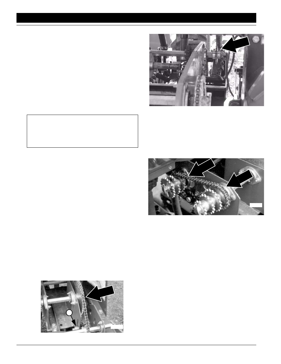
To change driver/driven ratio, refer to Figure 3-3..
Loosen and slide idler sprockets out of chain. Remove
lynch pins from shafts. Place correct sprockets on
shafts. Store sprockets not used on ends of shafts.
Reinstall chain and slide idlers back into place so
chain has 6 mm (1/4-inch) slack.
Figure 3-3
Driver/Driven Sprockets
4.
Raise drill with tractor hydraulics so the contact
wheels are not touching the gauge wheels. Rotate
drive gauge wheel to see that metering system is
working properly and free from foreign material.
5.
Check that your gauge-wheel tires are 13.0/55-16 12
PR AW and properly inflated. Refer to Tire Inflation
Chart, “Appendix,” page 40.
6.
Place several kilos (pounds) of fertilizer over three fer-
tilizer feed cups on outside end of drill box. Pull ferti-
lizer tubes off of these three disk openers.
7.
Weigh an empty container large enough to hold ferti-
lizer applied to one hectare (acre).
8.
Turn drive wheel until fertilizer starts to drop to ground.
9.
Place container under the three tubes to gather me-
tered fertilizer.
10. Turn drive gauge wheel 319 rotations for a one-hectare
seeding rate or 127 rotations for a one-acre seeding
rate. Check that feed cups have plenty of fertilizer com-
ing into them.
19T
21896
Dr
iven
Dr
iver
16378